
Network Device Installation Guide

Send documentation comments to mdsfeedback-doc@cisco.com.
2-40
Cisco MDS 9500 Series Hardware Installation Guide
OL-17467-02
Chapter 2 Installing the Cisco MDS 9500 Series
Removing, Installing, and Verifying Supervisor, Switching, and Services Modules
Installing Supervisor Modules
In a Cisco MDS 9513 Director, slots 7 and 8 are reserved for the Supervisor-2 modules. In the Cisco
MDS 9509 Director, slot
5 is reserved for the Supervisor-2 or Supervisor-1 module. In the Cisco MDS
9506 Director, slot
5 is reserved for the Supervisor-1 module. Slot 6 in the Cisco MDS 9509 and 9506
Directors is reserved for an additional redundant supervisor module in case the supervisor module in
slot
5 fails. See Figure 1-3 on page 1-6 and Figure 1-4 on page 1-7 for slot locations.
Supervisor-1 modules and Supervisor-2 modules cannot be used in the same switch, except for migration
purposes. Both the active and standby supervisor modules must be of the same type, either Supervisor-1
or Supervisor-2 modules. For Cisco MDS 9513 Directors, both supervisor modules must be Supervisor-2
modules.
Step 1 Before installing any modules in the chassis, Cisco recommends installing the chassis in the rack. See
the
“Installing the Chassis in a Cabinet or Rack” section on page 2-6.
Step 2 Verify that there is enough clearance to accommodate any cables or interface equipment that you want
to connect to the module.
Step 3 Verify that the captive screws are tightened to 8 in-lb on all modules already installed in the chassis. This
ensures that the EMI gaskets are fully compressed and maximizes the opening space for the module
being installed.
Step 4 If a filler panel is installed, remove the two Phillips pan-head screws from the filler panel and remove
the panel. To remove a currently installed module, see the
“Removing Other Switching and Services
Modules” section on page 2-45.
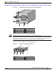
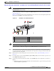
Step 5 Open both the ejector levers on the new or replacement module completely. (See Figure 2-22.)