S e n d d o c u m e n t a t i o n c o m m e n t s t o m d s f e e d b a ck - d o c @ c i s c o . c o m . Cisco MDS 9500 Series Hardware Installation Guide October 2008 Americas Headquarters Cisco Systems, Inc. 170 West Tasman Drive San Jose, CA 95134-1706 USA http://www.cisco.
S e n d d o c u m e n t a t i o n c o m m e n t s t o m d s f e e d b a ck - d o c @ c i s c o . c o m . THE SPECIFICATIONS AND INFORMATION REGARDING THE PRODUCTS IN THIS MANUAL ARE SUBJECT TO CHANGE WITHOUT NOTICE. ALL STATEMENTS, INFORMATION, AND RECOMMENDATIONS IN THIS MANUAL ARE BELIEVED TO BE ACCURATE BUT ARE PRESENTED WITHOUT WARRANTY OF ANY KIND, EXPRESS OR IMPLIED. USERS MUST TAKE FULL RESPONSIBILITY FOR THEIR APPLICATION OF ANY PRODUCTS.
S e n d d o c u m e n t a t i o n c o m m e n t s t o m d s f e e d b a ck - d o c @ c i s c o . c o m .
Contents S e n d d o c u m e n t a t i o n c o m m e n t s t o m d s f e e d b a ck - d o c @ c i s c o . c o m .
Contents S e n d d o c u m e n t a t i o n c o m m e n t s t o m d s f e e d b a ck - d o c @ c i s c o . c o m .
Contents S e n d d o c u m e n t a t i o n c o m m e n t s t o m d s f e e d b a ck - d o c @ c i s c o . c o m .
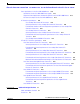
Contents S e n d d o c u m e n t a t i o n c o m m e n t s t o m d s f e e d b a ck - d o c @ c i s c o . c o m . A APPENDIX Migrating to Generation 3 8-Gbps Fibre Channel Switching Modules Overview A-1 A-1 Usage Guidelines A-2 Before You Begin Upgrading the MDS 9513 Director A-3 Migration Procedures for the MDS 9513 Director A-3 Installing the MDS 9000 4/44-Port 8-Gbps Host-Optimized Module A-3 Installing MDS 9513 Fabric 2 Modules and Running Cisco SAN-OS 3.
Contents S e n d d o c u m e n t a t i o n c o m m e n t s t o m d s f e e d b a ck - d o c @ c i s c o . c o m .
Contents S e n d d o c u m e n t a t i o n c o m m e n t s t o m d s f e e d b a ck - d o c @ c i s c o . c o m .
Contents S e n d d o c u m e n t a t i o n c o m m e n t s t o m d s f e e d b a ck - d o c @ c i s c o . c o m .
S e n d d o c u m e n t a t i o n c o m m e n t s t o m d s f e e d b a ck - d o c @ c i s c o . c o m . New and Changed Information This Cisco MDS 9500 Series Hardware Installation Guide applies to Cisco MDS NX-OS Release 4.1(1b) and earlier Cisco MDS SAN-OS releases. Table 1 lists the new and changed features available with each supported Cisco MDS NX-OS release and SAN-OS release for the Cisco MDS 9500 Series, with the latest release first. Note As of NX-OS Release 4.
New and Changed Information S e n d d o c u m e n t a t i o n c o m m e n t s t o m d s f e e d b a ck - d o c @ c i s c o . c o m . Table 1 Documented Features for the Cisco MDS 9500 Series (continued) Changed in Release Where Documented Feature Description Migration to Generation 3 modules Added the information associated with 4.1(1b) readying the MDS 9500 Series to support Generation 3 8-Gbps Fibre Channel switching modules.
New and Changed Information S e n d d o c u m e n t a t i o n c o m m e n t s t o m d s f e e d b a ck - d o c @ c i s c o . c o m . Table 1 Documented Features for the Cisco MDS 9500 Series (continued) Changed in Release Where Documented Feature Description Supervisor-2 module Added Supervisor-2 module. 3.0(1) Supervisor-2 modules can be used in the Cisco MDS 9509 and 9506 Director in slots 5 and 6. Dual Supervisor-2 modules must be used in slots 7 and 8 of the Cisco MDS 9513 Director.
New and Changed Information S e n d d o c u m e n t a t i o n c o m m e n t s t o m d s f e e d b a ck - d o c @ c i s c o . c o m . Table 1 Documented Features for the Cisco MDS 9500 Series (continued) Changed in Release Where Documented Feature Description 3000W Power Supply for the Cisco MDS 9509 Director Added 3000W power supply for the Cisco MDS 9509 Director. 3.0(1) Gigabit Ethernet SFP transceiver Added Gigabit Ethernet SFP transceiver.
New and Changed Information S e n d d o c u m e n t a t i o n c o m m e n t s t o m d s f e e d b a ck - d o c @ c i s c o . c o m . Table 1 Documented Features for the Cisco MDS 9500 Series (continued) Changed in Release Where Documented Feature Description Installation of SFP transceivers Added instructions for installation and Not release The “Removing, Installing, removal of SFP transceivers and cables. specific and Verifying Supervisor, Switching, and Services Modules” section on page 2-38.
New and Changed Information S e n d d o c u m e n t a t i o n c o m m e n t s t o m d s f e e d b a ck - d o c @ c i s c o . c o m .
S e n d d o c u m e n t a t i o n c o m m e n t s t o m d s f e e d b a ck - d o c @ c i s c o . c o m . Preface This preface describes the audience, organization, and conventions of the Cisco MDS 9500 Series Hardware Installation Guide. It also provides information on how to obtain related documentation. Audience To use this installation guide, you must be familiar with electronic circuitry and wiring practices and preferably be an electronic or electromechanical technician.
Preface S e n d d o c u m e n t a t i o n c o m m e n t s t o m d s f e e d b a ck - d o c @ c i s c o . c o m . Chapter Title Description Appendix E Cable and Port Specifications Lists cable and port specifications for the Cisco MDS 9500 Series switch. Appendix F Provides a site-planning checklist and sample maintenance and network records. Site Planning and Maintenance Records Conventions This document uses the following conventions for notes, cautions, and safety warnings.
Preface S e n d d o c u m e n t a t i o n c o m m e n t s t o m d s f e e d b a ck - d o c @ c i s c o . c o m . Attention Ce symbole d'avertissement indique un danger. Vous vous trouvez dans une situation pouvant causer des blessures ou des dommages corporels. Avant de travailler sur un équipement, soyez conscient des dangers posés par les circuits électriques et familiarisez-vous avec les procédures couramment utilisées pour éviter les accidents.
Preface S e n d d o c u m e n t a t i o n c o m m e n t s t o m d s f e e d b a ck - d o c @ c i s c o . c o m . Varning! Denna varningssymbol signalerar fara. Du befinner dig i en situation som kan leda till personskada. Innan du utför arbete på någon utrustning måste du vara medveten om farorna med elkretsar och känna till vanligt förfarande för att förebygga skador.
Preface S e n d d o c u m e n t a t i o n c o m m e n t s t o m d s f e e d b a ck - d o c @ c i s c o . c o m .
Preface S e n d d o c u m e n t a t i o n c o m m e n t s t o m d s f e e d b a ck - d o c @ c i s c o . c o m . Obtaining Documentation, Obtaining Support, and Security Guidelines For information on obtaining documentation, submitting a service request, and gathering additional information, see the monthly What’s New in Cisco Product Documentation, which also lists all new and revised Cisco technical documentation, at: http://www.cisco.com/en/US/docs/general/whatsnew/whatsnew.
S e n d d o c u m e n t a t i o n c o m m e n t s t o m d s f e e d b a ck - d o c @ c i s c o . c o m . CH A P T E R 1 Product Overview The Cisco MDS 9500 Multilayer Director elevates the standard for director-class switches. Providing industry-leading availability, scalability, security, and management, the Cisco MDS 9500 Series allows deployment of high-performance SANs with lowest total cost of ownership.
Chapter 1 Product Overview Chassis S e n d d o c u m e n t a t i o n c o m m e n t s t o m d s f e e d b a ck - d o c @ c i s c o . c o m .
Chapter 1 Product Overview Chassis S e n d d o c u m e n t a t i o n c o m m e n t s t o m d s f e e d b a ck - d o c @ c i s c o . c o m . Cisco MDS 9513 Director The Cisco MDS 9513 Director is a 13-slot Fibre Channel switch. The front panel consists of 13 horizontal slots, where slots 1 to 6 and slots 9 to 13 are reserved for switching and services modules only, and slots 7 and 8 are for Supervisor-2 modules only.
Chapter 1 Product Overview Chassis S e n d d o c u m e n t a t i o n c o m m e n t s t o m d s f e e d b a ck - d o c @ c i s c o . c o m .
Chapter 1 Product Overview Chassis S e n d d o c u m e n t a t i o n c o m m e n t s t o m d s f e e d b a ck - d o c @ c i s c o . c o m . Figure 1-2 Rear Panel 9513 Chassis 1 144426 2 5 4 3 1 Power supplies 4 Air vent panels 2 crossbar module fans 5 Clock module1 3 crossbar modules 1. Clock modules are located inside the air vent panel. You must remove the air vent panel to access the clock modules.
Chapter 1 Product Overview Chassis S e n d d o c u m e n t a t i o n c o m m e n t s t o m d s f e e d b a ck - d o c @ c i s c o . c o m . Cisco MDS 9509 Director The Cisco MDS 9509 Director has a 9-slot chassis as shown in Figure 1-3, and it supports the following: • Redundant Supervisor-2 modules with associated internal crossbar modules. • Up to two Supervisor-1 modules that provide a switching fabric, plus a console port, COM1 port, and a MGMT 10/100 Ethernet port on each module.
Chapter 1 Product Overview Chassis S e n d d o c u m e n t a t i o n c o m m e n t s t o m d s f e e d b a ck - d o c @ c i s c o . c o m . Cisco MDS 9506 Director The Cisco MDS 9506 Director has a 6-slot chassis as shown in Figure 1-4, and it supports the following: • Up to two Supervisor-1 modules that provide a switching fabric, with a console port, COM1 port, and a MGMT 10/100 Ethernet port on each module. Slots 5 and 6 are reserved for the supervisor modules.
Chapter 1 Product Overview Backplane and Clock Modules S e n d d o c u m e n t a t i o n c o m m e n t s t o m d s f e e d b a ck - d o c @ c i s c o . c o m . Backplane and Clock Modules The Cisco MDS 9500 Series includes one or more clock modules that are accessible from the back of the chassis. The Cisco MDS 9513 and 9509 Directors have two field-replaceable clock modules for redundancy and failover. The Cisco MDS 9506 Director has one field-replaceable clock module.
Chapter 1 Product Overview Cisco MDS Fibre Channel Switch for IBM Blade Center S e n d d o c u m e n t a t i o n c o m m e n t s t o m d s f e e d b a ck - d o c @ c i s c o . c o m . Cisco MDS Fibre Channel Switch for IBM Blade Center The Cisco MDS Fibre Channel Bladeswitch for IBM BladeCenter is designed for IBM BladeCenter environments.
Chapter 1 Product Overview Power Supplies S e n d d o c u m e n t a t i o n c o m m e n t s t o m d s f e e d b a ck - d o c @ c i s c o . c o m . Cisco MDS 9513 Power Supplies The Cisco MDS 9513 Director supports the 6000-W AC power supply (AC input). (See Figure 1-6.
Chapter 1 Product Overview Power Supplies S e n d d o c u m e n t a t i o n c o m m e n t s t o m d s f e e d b a ck - d o c @ c i s c o . c o m . Table 1-2 describes the LEDs for the Cisco MDS 9513 Director power supplies. Table 1-2 LEDs for the Cisco MDS 9513 Director Power Supplies LED Status Description Input 1 OK Green AC input at greater than 85 V is good and power supply is functioning normally if two single 110 V or one single 220 V are connected.
Chapter 1 Product Overview Power Supplies S e n d d o c u m e n t a t i o n c o m m e n t s t o m d s f e e d b a ck - d o c @ c i s c o . c o m . Cisco MDS 9509 Power Supplies The Cisco MDS 9509 Director supports the following types of power supplies: • 4000-W AC power supply (AC input and DC output) The 4000-W AC power supply has a permanently attached power cable, and it requires 220-VAC input. (See Figure 1-7.
Chapter 1 Product Overview Power Supplies S e n d d o c u m e n t a t i o n c o m m e n t s t o m d s f e e d b a ck - d o c @ c i s c o . c o m .
Chapter 1 Product Overview Power Supplies S e n d d o c u m e n t a t i o n c o m m e n t s t o m d s f e e d b a ck - d o c @ c i s c o . c o m .
Chapter 1 Product Overview Power Supplies S e n d d o c u m e n t a t i o n c o m m e n t s t o m d s f e e d b a ck - d o c @ c i s c o . c o m . Cisco MDS 9506 Power Supplies The Cisco MDS 9506 Director supports the following types of power supplies: • 1900-W AC power supply (AC input and DC output) • 1900-W DC power supply (DC input and DC output) Power is supplied to the Cisco MDS 9506 power supplies though PEMs in the front of the chassis.
Chapter 1 Product Overview Fan Modules S e n d d o c u m e n t a t i o n c o m m e n t s t o m d s f e e d b a ck - d o c @ c i s c o . c o m . Fan Modules The Cisco MDS 9513 Director has a front panel fan tray with 15 fans with an abrupt stop-to-fan rotation safety feature after power is disconnected or the fan tray is removed from the midplane. The Cisco MDS 9509 Director has a front panel fan module with nine fans and the Cisco MDS 9506 Director has a front panel fan module with six fans.
Chapter 1 Product Overview Supervisor Modules S e n d d o c u m e n t a t i o n c o m m e n t s t o m d s f e e d b a ck - d o c @ c i s c o . c o m . Supervisor-2 Modules The Cisco MDS 9500 Series offers redundant, hot-swappable, Supervisor-2 modules. (See Figure 1-12.) Supervisor-2 modules can be used in the Cisco MDS 9509 and 9506 Directors in slots 5 and 6. Supervisor-2 modules must be used in slots 7 and 8 of the Cisco MDS 9513 Director.
Chapter 1 Product Overview Supervisor Modules S e n d d o c u m e n t a t i o n c o m m e n t s t o m d s f e e d b a ck - d o c @ c i s c o . c o m . Control and Management The Supervisor-2 modules provide the following control and management features: • A redundant central arbiter that provides traffic control and access fairness. • A nondisruptive restart of a single failing process on the same supervisor.
Chapter 1 Product Overview Supervisor Modules S e n d d o c u m e n t a t i o n c o m m e n t s t o m d s f e e d b a ck - d o c @ c i s c o . c o m . Caution • Two USB ports provide a simple interface allowing you to connect to different devices supported by Cisco MDS NX-OS. On the double decker connector, USB port 1 is on the lower position and port 2 is on the upper position. • Supervisor CPU subsystem based on Motorola PowerPC 7447.
Chapter 1 Product Overview Supervisor Modules S e n d d o c u m e n t a t i o n c o m m e n t s t o m d s f e e d b a ck - d o c @ c i s c o . c o m . Table 1-4 LEDs for the Cisco MDS 9500 Series Supervisor-2 Modules LED Status Description Status Green All diagnostics pass. The module is operational (normal initialization sequence). Orange One of the following occurs: Red System Green • The module is booting or running diagnostics (normal initialization sequence).
Chapter 1 Product Overview Supervisor Modules S e n d d o c u m e n t a t i o n c o m m e n t s t o m d s f e e d b a ck - d o c @ c i s c o . c o m . Supervisor-1 Modules The Cisco MDS 9509 and 9506 Directors support up to two Supervisor-1 or Supervisor-2 modules that can be installed in slots 5 and 6 only.
Chapter 1 Product Overview Supervisor Modules S e n d d o c u m e n t a t i o n c o m m e n t s t o m d s f e e d b a ck - d o c @ c i s c o . c o m . If the kernel service cannot perform a warm restart of the process, it issues a cold restart. • A nondisruptive switchover from the active supervisor to a redundant standby without loss of traffic. If the supervisor module has to be restarted, then the secondary supervisor (which is continuously monitoring the primary) takes over.
Chapter 1 Product Overview Supervisor Modules S e n d d o c u m e n t a t i o n c o m m e n t s t o m d s f e e d b a ck - d o c @ c i s c o . c o m . • Caution CompactFlash slot for an optional CompactFlash card. The optional card can be used for storing additional software images and configuration, debugging, and syslog information. Use only the CompactFlash devices that are certified for use with Cisco MDS switches and are formatted using Cisco MDS switches.
Chapter 1 Product Overview Supervisor Modules S e n d d o c u m e n t a t i o n c o m m e n t s t o m d s f e e d b a ck - d o c @ c i s c o . c o m . Table 1-5 LEDs for the Cisco MDS 9500 Series Supervisor Modules LED Status Description Status Green All diagnostics pass. The module is operational (normal initialization sequence). Orange One of the following occurs: Red System1 Green • The module is booting or running diagnostics (normal initialization sequence).
Chapter 1 Product Overview Crossbar Modules S e n d d o c u m e n t a t i o n c o m m e n t s t o m d s f e e d b a ck - d o c @ c i s c o . c o m . Crossbar Modules The Cisco MDS 9513 Director supports two external crossbar modules located at the rear of the chassis. Each Supervisor-2 module has an associated external crossbar module for redundancy. The Supervisor-2 module in slot 7 is associated with crossbar module 1 and Supervisor-2 in slot 8 is associated with crossbar module 2.
Chapter 1 Product Overview Crossbar Modules S e n d d o c u m e n t a t i o n c o m m e n t s t o m d s f e e d b a ck - d o c @ c i s c o . c o m . Table 1-6 LEDs for the Cisco MDS 9500 Crossbar Modules LED Status Description Status Green All diagnostics pass. The module is operational (normal initialization sequence). Orange One of the following occurs: Red • The module is booting or running diagnostics (normal initialization sequence).
Chapter 1 Product Overview Cisco MDS 9000 Series Module Compatibility S e n d d o c u m e n t a t i o n c o m m e n t s t o m d s f e e d b a ck - d o c @ c i s c o . c o m . Cisco MDS 9000 Series Module Compatibility Table 1-7 lists the hardware modules available and the chassis compatibility associated with them.
Chapter 1 Product Overview Port Index Availability S e n d d o c u m e n t a t i o n c o m m e n t s t o m d s f e e d b a ck - d o c @ c i s c o . c o m . Port Index Availability The Cisco MDS 9500 Multilayer Directors are designed to operate with any combination of Cisco MDS 9000 modules. However, you should be aware of the maximum port availability your chassis can support. A port index is an internally assigned number that Cisco NX-OS uses to switch data packets within the director or fabric switch.
Chapter 1 Product Overview Port Index Availability S e n d d o c u m e n t a t i o n c o m m e n t s t o m d s f e e d b a ck - d o c @ c i s c o . c o m . means that while there may be enough port indexes available for a Generation 1 module, the module may not boot up because the available port indexes are not in a contiguous range or the contiguous block does not start at the first port index for a given slot.
Chapter 1 Product Overview Port Index Availability S e n d d o c u m e n t a t i o n c o m m e n t s t o m d s f e e d b a ck - d o c @ c i s c o . c o m .
Chapter 1 Product Overview Port Index Availability S e n d d o c u m e n t a t i o n c o m m e n t s t o m d s f e e d b a ck - d o c @ c i s c o . c o m .
Chapter 1 Product Overview Switching Modules S e n d d o c u m e n t a t i o n c o m m e n t s t o m d s f e e d b a ck - d o c @ c i s c o . c o m . Table 1-12 Maximum Chassis Configuration on a Cisco MDS 9513 Director (Valid) (continued) Slot No.
Chapter 1 Product Overview Switching Modules S e n d d o c u m e n t a t i o n c o m m e n t s t o m d s f e e d b a ck - d o c @ c i s c o . c o m . 48-port 8-Gbps Fibre Channel Switching Module The 48-Port 8-Gbps Fibre Channel switching module offers 48 autosensing 1-, 2-, 4- and 8-Gbps Fibre Channel ports and can be used in the Cisco MDS 9500 Series Switches. The 48-port switching module can be configured in one of two operational modes: shared bandwidth mode (default) and dedicated bandwidth mode.
Chapter 1 Product Overview Switching Modules S e n d d o c u m e n t a t i o n c o m m e n t s t o m d s f e e d b a ck - d o c @ c i s c o . c o m . 4/44-port 8-Gbps Host-Optimized Fibre Channel Switching Module 188657 Figure 1-19 48-Port 4-Gbps Fibre Channel Switching Module The 48-port 4-Gbps Fibre Channel switching module offers 48 autosensing 1-, 2-, and 4-Gbps Fibre Channel ports and can be used in any of the Cisco MDS 9500 Series chassis and in the Cisco MDS 9216i and 9216A Switches.
Chapter 1 Product Overview Switching Modules S e n d d o c u m e n t a t i o n c o m m e n t s t o m d s f e e d b a ck - d o c @ c i s c o . c o m . 24-port 4-Gbps Fibre Channel Switching Module The 24-port 4-Gbps Fibre Channel switching module offers 24 autosensing 1-, 2-, and 4-Gbps Fibre Channel ports and can be used in any of the Cisco MDS 9500 Series chassis and in the Cisco MDS 9216i and 9216A Switches.
Chapter 1 Product Overview Switching Modules S e n d d o c u m e n t a t i o n c o m m e n t s t o m d s f e e d b a ck - d o c @ c i s c o . c o m . 4-port 10-Gbps Fibre Channel Switching Module The 4-port 10-Gbps Fibre Channel switching module offers four dedicated bandwidth Fibre Channel ports running at 10 Gbps with no oversubscription. This module can be used in any of the Cisco MDS 9500 Series chassis and in the Cisco MDS 9216i and 9216A Switches.
Chapter 1 Product Overview Switching Modules S e n d d o c u m e n t a t i o n c o m m e n t s t o m d s f e e d b a ck - d o c @ c i s c o . c o m . LEDs on the Generation 2 Switching Modules Table 1-13 describes the LEDs for the 48-port, 24-port, and 12-port 4-Gbps Fibre Channel switching modules and the 4-port 10-Gbps Fibre Channel switching module.
Chapter 1 Product Overview Switching Modules S e n d d o c u m e n t a t i o n c o m m e n t s t o m d s f e e d b a ck - d o c @ c i s c o . c o m . Tip For a full 2-Gbps bandwidth between two hosts, connect one host to the first port group and the second host to the second port group.
Chapter 1 Product Overview Switching Modules S e n d d o c u m e n t a t i o n c o m m e n t s t o m d s f e e d b a ck - d o c @ c i s c o . c o m . Switching Module Features Each switching module draws its power from the 42 V supplied on the backplane with local DC/DC power converters and regulators. The control processor on the switching module provides power-on, offline, and online diagnostics.
Chapter 1 Product Overview Switching Modules S e n d d o c u m e n t a t i o n c o m m e n t s t o m d s f e e d b a ck - d o c @ c i s c o . c o m . LEDs on the Generation 1 Switching Module Table 1-14 describes the LEDs for the 16-port and 32-port switching modules. Table 1-14 LED LEDs for the Cisco MDS 9000 Family Generation 1 Fibre Channel Switching Modules Status Status Green Orange Red Speed Description All diagnostics pass. The module is operational (normal initialization sequence).
Chapter 1 Product Overview Services Modules S e n d d o c u m e n t a t i o n c o m m e n t s t o m d s f e e d b a ck - d o c @ c i s c o . c o m .
Chapter 1 Product Overview Services Modules S e n d d o c u m e n t a t i o n c o m m e n t s t o m d s f e e d b a ck - d o c @ c i s c o . c o m . 18/4-Port Multiservice Federal Information Processing Standards Module The Cisco MDS 9000 Family 18/4-port Multiservice FIPS (MSFM-18/4) module is a FIPS 140-2 Level 3-compliant version of the MSM-18/4 module.
Chapter 1 Product Overview Services Modules S e n d d o c u m e n t a t i o n c o m m e n t s t o m d s f e e d b a ck - d o c @ c i s c o . c o m . LEDs on the 18/4-Port Multiservice Module Table 1-15 describes the LEDs for the 18/4-port Multiservice module. Table 1-15 LED Status Status Green Orange Red Link LEDs for the Cisco MDS 9000 Family 18/4-Port Multiservice Modules Description All diagnostics pass. The module is operational (normal initialization sequence).
Chapter 1 Product Overview Services Modules S e n d d o c u m e n t a t i o n c o m m e n t s t o m d s f e e d b a ck - d o c @ c i s c o . c o m . 14/2-Port Multiprotocol Services Module The 14/2-port Multiprotocol Services (MPS-14/2) module provides 14 2-Gbps Fibre Channel autosensing ports and two 1-Gigabit Ethernet ports for iSCSI and FCIP over Gigabit Ethernet. The MPS-14/2 module supports the intelligent features available on other modules, including VSANs, security, and traffic management.
Chapter 1 Product Overview Services Modules S e n d d o c u m e n t a t i o n c o m m e n t s t o m d s f e e d b a ck - d o c @ c i s c o . c o m . Figure 1-28 shows an MPS-14/2 module.
Chapter 1 Product Overview Services Modules S e n d d o c u m e n t a t i o n c o m m e n t s t o m d s f e e d b a ck - d o c @ c i s c o . c o m . Table 1-16 LEDs for the Cisco MDS 9000 Family MPS-14/2 Modules (continued) LED Status Description Link Solid green Link is up. Flashing Link is up (beacon used to identify port). green Solid yellow Link is disabled by software. Flashing A fault condition exists. yellow Off No link.
Chapter 1 Product Overview Services Modules S e n d d o c u m e n t a t i o n c o m m e n t s t o m d s f e e d b a ck - d o c @ c i s c o . c o m . Figure 1-30 shows the IPS-4 services module. Figure 1-30 Cisco MDS 9000 Family IPS-4 Services Module 1 2 LINK 3 LINK LINK 1 113161 2 4 LINK 4 3 1 Status LED 3 Link LEDs 2 Gigabit Ethernet ports 4 Asset tag LEDs on IP Storage Services Modules Table 1-17 describes the LEDs for the IPS services modules.
Chapter 1 Product Overview Services Modules S e n d d o c u m e n t a t i o n c o m m e n t s t o m d s f e e d b a ck - d o c @ c i s c o . c o m . 32-Port Fibre Channel Advanced Services Module The Cisco MDS 9000 Family 32-port Fibre Channel Advanced Services Module (ASM) enables pooling of heterogeneous storage for increased storage utilization, simplified storage management, and reduced total cost of storage ownership.
Chapter 1 Product Overview Services Modules S e n d d o c u m e n t a t i o n c o m m e n t s t o m d s f e e d b a ck - d o c @ c i s c o . c o m . Note Software downloads are only necessary when a revision of the code is needed. The supervisor module can force a reset on the services module and controls whether power is applied to the switching module.
Chapter 1 Product Overview Services Modules S e n d d o c u m e n t a t i o n c o m m e n t s t o m d s f e e d b a ck - d o c @ c i s c o . c o m . 32-Port Fibre Channel Storage Services Module The 32-port Fibre Channel Storage Services Module (SSM) for the Cisco MDS 9000 Family supports up to 32 Fibre Channel ports, provides distributed intelligent storage services, and supports future storage services. Note Cisco MDS 9500 Series switches running Cisco MDS SAN-OS Release 2.x, 3.
Chapter 1 Product Overview Services Modules S e n d d o c u m e n t a t i o n c o m m e n t s t o m d s f e e d b a ck - d o c @ c i s c o . c o m . If a single component or a set of components on the switching module fails, this failure will not disable another switching module if that is the only failure in the system. For the detection of most component failures, each switching module has a hardware watchdog timer that resets the card if is not serviced periodically.
Chapter 1 Product Overview Services Modules S e n d d o c u m e n t a t i o n c o m m e n t s t o m d s f e e d b a ck - d o c @ c i s c o . c o m . Caching Services Module The Caching Services Module (CSM) provides virtualization services that allow the Cisco MDS 9000 Family switches to reallocate physical resources as virtual resources for increased efficiency. The CSM receives and sends data through the switch backplane.
Chapter 1 Product Overview Services Modules S e n d d o c u m e n t a t i o n c o m m e n t s t o m d s f e e d b a ck - d o c @ c i s c o . c o m . Figure 1-34 CSM, Internal View 4 2 3 94038 1 1 Disk drive 2 3 Battery 2 2 Disk drive 1 4 Battery 1 See the “Installing a Switching or Services Module, Including Caching Services Modules” section on page 2-45 for information about installing the CSM and maintaining the CSM batteries.
Chapter 1 Product Overview Services Modules S e n d d o c u m e n t a t i o n c o m m e n t s t o m d s f e e d b a ck - d o c @ c i s c o . c o m . LEDs on the Caching Services Module Table 1-20 describes the LEDs for the CSM. Table 1-20 LEDs for the Cisco MDS 9000 Family CSM LED Status Description Status Green All diagnostics pass, and the module is operational (normal initialization sequence).
Chapter 1 Product Overview Supported Transceivers S e n d d o c u m e n t a t i o n c o m m e n t s t o m d s f e e d b a ck - d o c @ c i s c o . c o m .
Chapter 1 Product Overview Supported Transceivers S e n d d o c u m e n t a t i o n c o m m e n t s t o m d s f e e d b a ck - d o c @ c i s c o . c o m . Fibre Channel SFP Transceivers Cisco Fibre Channel SFP transceivers are available in SWL or LWL versions. Both of these versions are 1-Gbps/2-Gbps/4-Gbps capable. Cisco Fibre Channel SFP+ transceivers are available in SWL or LWL versions. Both of these versions are 2-Gbps/4-Gbps/8-Gbps capable.
Chapter 1 Product Overview Supported Transceivers S e n d d o c u m e n t a t i o n c o m m e n t s t o m d s f e e d b a ck - d o c @ c i s c o . c o m . For more information about Gigabit Ethernet SFP transceiver specifications, see the “SFP and SFP+ Transceiver Specifications” section on page D-22. DWDM Fibre Channel SFP Transceivers The Cisco DWDM SFP transceivers have LC connectors and support 1-Gbps/2-Gbps Fibre Channel.
Chapter 1 Product Overview Supported Transceivers S e n d d o c u m e n t a t i o n c o m m e n t s t o m d s f e e d b a ck - d o c @ c i s c o . c o m .
S e n d d o c u m e n t a t i o n c o m m e n t s t o m d s f e e d b a ck - d o c @ c i s c o . c o m .
Chapter 2 Installing the Cisco MDS 9500 Series Preinstallation S e n d d o c u m e n t a t i o n c o m m e n t s t o m d s f e e d b a ck - d o c @ c i s c o . c o m . Warning Only trained and qualified personnel should be allowed to install, replace, or service this equipment. Statement 1030 Warning A readily accessible two-poled disconnect device must be incorporated in the fixed wiring.
Chapter 2 Installing the Cisco MDS 9500 Series Preinstallation S e n d d o c u m e n t a t i o n c o m m e n t s t o m d s f e e d b a ck - d o c @ c i s c o . c o m .
Chapter 2 Installing the Cisco MDS 9500 Series Preinstallation S e n d d o c u m e n t a t i o n c o m m e n t s t o m d s f e e d b a ck - d o c @ c i s c o . c o m . Caution • Avoid UPS types that use ferroresonant technology. These UPS types can become unstable with systems such as the Cisco MDS 9000 Family, which can have substantial current draw fluctuations because of fluctuating data traffic patterns. Ensure that circuits are sized according to local and national codes.
Chapter 2 Installing the Cisco MDS 9500 Series Preinstallation S e n d d o c u m e n t a t i o n c o m m e n t s t o m d s f e e d b a ck - d o c @ c i s c o . c o m . Required Equipment Gather the following items before beginning the installation: • Number 1 and number 2 Phillips screwdrivers with torque capability. • 3/16-inch flat-blade screwdriver. • Tape measure and level. • ESD wrist strap or other grounding device. • Antistatic mat or antistatic foam.
Chapter 2 Installing the Cisco MDS 9500 Series Installing the Chassis in a Cabinet or Rack S e n d d o c u m e n t a t i o n c o m m e n t s t o m d s f e e d b a ck - d o c @ c i s c o . c o m . Tip Keep the shipping container for use when moving or shipping the chassis in the future. The shipping carton can be flattened and stored with the pallet. Note If you purchased this product through a Cisco reseller, contact the reseller directly for technical support.
Chapter 2 Installing the Cisco MDS 9500 Series Installing the Chassis in a Cabinet or Rack S e n d d o c u m e n t a t i o n c o m m e n t s t o m d s f e e d b a ck - d o c @ c i s c o . c o m . Note You can remove the modules and other field-replaceable components to make moving and positioning the chassis easier and safer. See the “Removing, Installing, and Verifying Supervisor, Switching, and Services Modules” section on page 2-38 for instructions specific to the component.
Chapter 2 Installing the Cisco MDS 9500 Series Installing the Chassis in a Cabinet or Rack S e n d d o c u m e n t a t i o n c o m m e n t s t o m d s f e e d b a ck - d o c @ c i s c o . c o m . Note If you are using the cable management bracket shipped with the switch, do not install the top four screws into the front right of the bracket. However, you must install the bottom screw (see Figure 2-1). The top four screws will be used to install the cable management bracket to the rail.
Chapter 2 Installing the Cisco MDS 9500 Series Installing the Chassis in a Cabinet or Rack S e n d d o c u m e n t a t i o n c o m m e n t s t o m d s f e e d b a ck - d o c @ c i s c o . c o m . Figure 2-2 Positioning the Support Bars 3 1 3 1 146034 2 1 2 1 1 Screws 3 2 Rack-mount support bracket Step 4 Rack-mount support bar Once the support bars are installed, secure the rack-mount support brackets to the rack using the screws provided.
Chapter 2 Installing the Cisco MDS 9500 Series Installing the Chassis in a Cabinet or Rack S e n d d o c u m e n t a t i o n c o m m e n t s t o m d s f e e d b a ck - d o c @ c i s c o . c o m . Securing the Rack-Mount Support Brackets 146036 Figure 2-3 Step 5 Position a person at each side of the chassis and one at the mechanical lift. Place the chassis on the lift by lifting on the top front of rear of the chassis.
Chapter 2 Installing the Cisco MDS 9500 Series Installing the Chassis in a Cabinet or Rack S e n d d o c u m e n t a t i o n c o m m e n t s t o m d s f e e d b a ck - d o c @ c i s c o . c o m .
Chapter 2 Installing the Cisco MDS 9500 Series Installing the Chassis in a Cabinet or Rack S e n d d o c u m e n t a t i o n c o m m e n t s t o m d s f e e d b a ck - d o c @ c i s c o . c o m . Note The rack-mount kit for the Cisco MDS 9509 Director includes side rack-mount brackets, which are required for the duration of the installation only and can be removed once the front rack-mount brackets are securely fastened to the rack-mounting rails.
Chapter 2 Installing the Cisco MDS 9500 Series Installing the Chassis in a Cabinet or Rack S e n d d o c u m e n t a t i o n c o m m e n t s t o m d s f e e d b a ck - d o c @ c i s c o . c o m . Figure 2-5 Installing the Side Rack-Mount Brackets for the Cisco MDS 9509 Chassis 2 1 94997 1 1 Step 3 2 Side rack-mount bracket Screws, 12-24 or 10-32 Attach the crossbar to the back of the side rack-mount brackets using one M3 x 8-mm screw per side as shown in Figure 2-6.
Chapter 2 Installing the Cisco MDS 9500 Series Installing the Chassis in a Cabinet or Rack S e n d d o c u m e n t a t i o n c o m m e n t s t o m d s f e e d b a ck - d o c @ c i s c o . c o m . Installing the Cisco MDS 9509 Chassis in the Rack 1 Step 5 1 Crossbar 2 Mounting rail 3 3 Side rack-mount bracket If you are installing the optional cable management bracket, place the cable management bracket in front of the front right rack-mount brackets.
Chapter 2 Installing the Cisco MDS 9500 Series Installing the Chassis in a Cabinet or Rack S e n d d o c u m e n t a t i o n c o m m e n t s t o m d s f e e d b a ck - d o c @ c i s c o . c o m .
Chapter 2 Installing the Cisco MDS 9500 Series Installing the Chassis in a Cabinet or Rack S e n d d o c u m e n t a t i o n c o m m e n t s t o m d s f e e d b a ck - d o c @ c i s c o . c o m . Table 2-3 Contents of Cisco MDS 9506 Rack-Mount Kit Quantity Part Description 14 12-24 x 3/4-in. Phillips binder-head screws 14 10-32 x 3/4-in.
Chapter 2 Installing the Cisco MDS 9500 Series System Grounding S e n d d o c u m e n t a t i o n c o m m e n t s t o m d s f e e d b a ck - d o c @ c i s c o . c o m . To install the Cisco MDS 9506 chassis in the rack using the rack-mount kit, follow these steps: Step 1 Place all the parts and screwdrivers near the rack for easy access while attaching the switch to the rack. Note The front rack-mount brackets are shipped installed on the switch.
Chapter 2 Installing the Cisco MDS 9500 Series System Grounding S e n d d o c u m e n t a t i o n c o m m e n t s t o m d s f e e d b a ck - d o c @ c i s c o . c o m . Table 2-4 Grounding Best Practices Environment Commercial building is subjected to direct lightning strikes. Electromagnetic Noise Severity Level High All lightning protection devices must be installed in strict accordance with manufacturer recommendations.
Chapter 2 Installing the Cisco MDS 9500 Series System Grounding S e n d d o c u m e n t a t i o n c o m m e n t s t o m d s f e e d b a ck - d o c @ c i s c o . c o m . Note In all situations, grounding practices must comply with local National Electric Code (NEC) requirements or local laws and regulations. Note Always ensure that all of the modules are completely installed and that the captive installation screws are fully tightened.
Chapter 2 Installing the Cisco MDS 9500 Series System Grounding S e n d d o c u m e n t a t i o n c o m m e n t s t o m d s f e e d b a ck - d o c @ c i s c o . c o m . Step 2 Grasp the spring or alligator clip on the ESD wrist strap and momentarily touch the clip to a bare metal spot (unpainted surface) on the rack. Cisco recommends that you touch the clip to an unpainted rack rail so that any built-up static charge is then safely dissipated to the entire rack.
Chapter 2 Installing the Cisco MDS 9500 Series System Grounding S e n d d o c u m e n t a t i o n c o m m e n t s t o m d s f e e d b a ck - d o c @ c i s c o . c o m . Figure 2-10 Attaching the ESD Wrist Strap to the System Ground Lug Screw 2 pt 5 1 2 4 133947 3 1 ESD ground strap 4 Clip installed (behind screw) 2 Clip and grounding lug 5 System ground connector 3 Side view of grounding lug (clip slid behind screw) c.
Chapter 2 Installing the Cisco MDS 9500 Series System Grounding S e n d d o c u m e n t a t i o n c o m m e n t s t o m d s f e e d b a ck - d o c @ c i s c o . c o m . – Never attempt to remove the printed circuit board from the metal carrier. Caution For safety reasons, check the resistance value of the antistatic strap periodically. The measurement should be between 1 and 10 megohm (Mohm).
Chapter 2 Installing the Cisco MDS 9500 Series Grounding the Chassis S e n d d o c u m e n t a t i o n c o m m e n t s t o m d s f e e d b a ck - d o c @ c i s c o . c o m . • Grounding wire—Not supplied as part of accessory kit. The grounding wire should be sized according to local and national installation requirements. Depending on the power supply and system, a 12 AWG to 6 AWG copper conductor is required for U.S. installations. Commercially available 6 AWG wire is recommended.
Chapter 2 Installing the Cisco MDS 9500 Series Grounding the Chassis S e n d d o c u m e n t a t i o n c o m m e n t s t o m d s f e e d b a ck - d o c @ c i s c o . c o m . System Ground Location on the Cisco MDS 9513 Chassis (Front) 144510 Figure 2-11 4 3 1 5 2 1 Grounding cable 4 Close-up of grounding pad on switch 2 Screws, M4, with square cone washers 5 ESD plug 3 NRTL listed grounding lug Figure 2-12 shows the ESD ground location on the rear panel of the Cisco MDS 9513 chassis.
Chapter 2 Installing the Cisco MDS 9500 Series Grounding the Chassis S e n d d o c u m e n t a t i o n c o m m e n t s t o m d s f e e d b a ck - d o c @ c i s c o . c o m . ESD Ground Location on the Cisco MDS 9513 Chassis (Rear) 144509 Figure 2-12 1 1 Caution ESD plug 2 2 ESD socket All power supplies must be grounded.
Chapter 2 Installing the Cisco MDS 9500 Series Grounding the Chassis S e n d d o c u m e n t a t i o n c o m m e n t s t o m d s f e e d b a ck - d o c @ c i s c o . c o m .
Chapter 2 Installing the Cisco MDS 9500 Series Grounding the Chassis S e n d d o c u m e n t a t i o n c o m m e n t s t o m d s f e e d b a ck - d o c @ c i s c o . c o m .
Chapter 2 Installing the Cisco MDS 9500 Series Starting Up the Switch S e n d d o c u m e n t a t i o n c o m m e n t s t o m d s f e e d b a ck - d o c @ c i s c o . c o m . Starting Up the Switch This section provides the following information: Warning Caution Note • Connecting the Power Supplies, page 2-28 • Powering Up the Switch and Verifying Component Installation, page 2-36 Hazardous voltage or energy is present on the backplane when the system is operating. Use caution when servicing.
Chapter 2 Installing the Cisco MDS 9500 Series Starting Up the Switch S e n d d o c u m e n t a t i o n c o m m e n t s t o m d s f e e d b a ck - d o c @ c i s c o . c o m . Providing Power to an AC Power Supply for the Cisco MDS 9513 Director To provide power to an AC power supply in a Cisco MDS 9513 Director, follow these steps: Step 1 Plug the power cable into the power supply, and tighten the screw on the cable retention device to ensure that the cable cannot be pulled out.
Chapter 2 Installing the Cisco MDS 9500 Series Starting Up the Switch S e n d d o c u m e n t a t i o n c o m m e n t s t o m d s f e e d b a ck - d o c @ c i s c o . c o m . Providing Power to an AC Power Supply for the Cisco MDS 9509 and Cisco MDS 9506 Directors The basic procedure for providing power to an AC power supply is the same for both a Cisco MDS 9509 Director and a Cisco MDS 9506 Director. Figure 2-16 shows a 2500-W AC power supply for the Cisco MDS 9509 Director.
Chapter 2 Installing the Cisco MDS 9500 Series Starting Up the Switch S e n d d o c u m e n t a t i o n c o m m e n t s t o m d s f e e d b a ck - d o c @ c i s c o . c o m .
Chapter 2 Installing the Cisco MDS 9500 Series Starting Up the Switch S e n d d o c u m e n t a t i o n c o m m e n t s t o m d s f e e d b a ck - d o c @ c i s c o . c o m . Figure 2-19 shows a power supply for a Cisco MDS 9506 Director. The power supply has no power connector. The power connector is provided on the PEM. The AC and DC power supplies are similar in appearance except for the label, which indicates whether it is AC or DC.
Chapter 2 Installing the Cisco MDS 9500 Series Starting Up the Switch S e n d d o c u m e n t a t i o n c o m m e n t s t o m d s f e e d b a ck - d o c @ c i s c o . c o m . Providing Power to a DC Power Supply in the Cisco MDS 9509 Director Warning Before performing any of the following procedures, ensure that power is removed from the DC circuit. Statement 1003 Warning When installing or replacing the unit, the ground connection must always be made first and disconnected last.
Chapter 2 Installing the Cisco MDS 9500 Series Starting Up the Switch S e n d d o c u m e n t a t i o n c o m m e n t s t o m d s f e e d b a ck - d o c @ c i s c o . c o m . Step 2 Ensure that the system (earth) ground connection is made. See the “System Grounding” section on page 2-17. Step 3 Turn the power switch on the power supply to off (0). Step 4 Unfasten the two screws securing the terminal block cover and pull the cover off the terminal block.
Chapter 2 Installing the Cisco MDS 9500 Series Starting Up the Switch S e n d d o c u m e n t a t i o n c o m m e n t s t o m d s f e e d b a ck - d o c @ c i s c o . c o m . Warning When installing or replacing the unit, the ground connection must always be made first and disconnected last. Statement 1046 For more information on DC power supply in the MDS 9506 Director, see the “System Grounding” section on page 2-17.
Chapter 2 Installing the Cisco MDS 9500 Series Starting Up the Switch S e n d d o c u m e n t a t i o n c o m m e n t s t o m d s f e e d b a ck - d o c @ c i s c o . c o m . b. Strip the cable ends to allow for metal-to-metal contact. Insert each cable into a separate ring lug, and crimp the lugs around the cables. c.
Chapter 2 Installing the Cisco MDS 9500 Series Starting Up the Switch S e n d d o c u m e n t a t i o n c o m m e n t s t o m d s f e e d b a ck - d o c @ c i s c o . c o m . To power up the switch and verify hardware operation, follow these steps: Step 1 Verify that the faceplates of all modules are flush with the front of the chassis, and the ejector levers are fully closed and approximately parallel to the faceplate of the module.
Chapter 2 Installing the Cisco MDS 9500 Series Removing, Installing, and Verifying Supervisor, Switching, and Services Modules S e n d d o c u m e n t a t i o n c o m m e n t s t o m d s f e e d b a ck - d o c @ c i s c o . c o m . Note If you purchased this product through a Cisco reseller, contact the reseller directly for technical support. If you purchased this product directly from Cisco Systems, contact Cisco Technical Support at this URL: http://www.cisco.com/warp/public/687/Directory/DirTAC.
Chapter 2 Installing the Cisco MDS 9500 Series Removing, Installing, and Verifying Supervisor, Switching, and Services Modules S e n d d o c u m e n t a t i o n c o m m e n t s t o m d s f e e d b a ck - d o c @ c i s c o . c o m . Caution To prevent ESD damage, wear grounding wrist straps during these procedures and handle modules by the carrier edges only. Note Install the Cisco MDS 9500 Series chassis in the rack before installing modules.
Chapter 2 Installing the Cisco MDS 9500 Series Removing, Installing, and Verifying Supervisor, Switching, and Services Modules S e n d d o c u m e n t a t i o n c o m m e n t s t o m d s f e e d b a ck - d o c @ c i s c o . c o m . Installing Supervisor Modules In a Cisco MDS 9513 Director, slots 7 and 8 are reserved for the Supervisor-2 modules. In the Cisco MDS 9509 Director, slot 5 is reserved for the Supervisor-2 or Supervisor-1 module.
Chapter 2 Installing the Cisco MDS 9500 Series Removing, Installing, and Verifying Supervisor, Switching, and Services Modules S e n d d o c u m e n t a t i o n c o m m e n t s t o m d s f e e d b a ck - d o c @ c i s c o . c o m . Figure 2-22 Positioning a Module in the Chassis 1 2 3 4 4 5 6 6 94987 3 4 Step 6 1 Slot guides 3 EMI Gasket 2 EMI Gasket 4 Ejector level (fully extended) Position the module in the chassis as follows: a.
Chapter 2 Installing the Cisco MDS 9500 Series Removing, Installing, and Verifying Supervisor, Switching, and Services Modules S e n d d o c u m e n t a t i o n c o m m e n t s t o m d s f e e d b a ck - d o c @ c i s c o . c o m . Figure 2-23 Clearing the EMI Gasket Press down gently 91690 Press down gently 4 WS-C6500-SFM 5 SWITCH FABIR D MDL 6 b.
Chapter 2 Installing the Cisco MDS 9500 Series Removing, Installing, and Verifying Supervisor, Switching, and Services Modules S e n d d o c u m e n t a t i o n c o m m e n t s t o m d s f e e d b a ck - d o c @ c i s c o . c o m . Closing the Ejector Levers 99331 Figure 2-24 Ejector levers flush with module faceplate Caution c. Note d. Do not press down too forcefully on the levers because they can bend.
Chapter 2 Installing the Cisco MDS 9500 Series Removing, Installing, and Verifying Supervisor, Switching, and Services Modules S e n d d o c u m e n t a t i o n c o m m e n t s t o m d s f e e d b a ck - d o c @ c i s c o . c o m . Removing a Caching Services Module Note A minimum of two CSMs in each fabric are required for redundancy and data backup. Warning Do not touch or bridge the metal contacts on the battery. Unintentional discharge of the batteries can cause serious burns.
Chapter 2 Installing the Cisco MDS 9500 Series Removing, Installing, and Verifying Supervisor, Switching, and Services Modules S e n d d o c u m e n t a t i o n c o m m e n t s t o m d s f e e d b a ck - d o c @ c i s c o . c o m . Removing Other Switching and Services Modules To remove a switching or services module from the chassis, follow these steps: Step 1 Disconnect any network interface cables attached to the module. Step 2 Loosen the two captive screws on the module being removed.
Chapter 2 Installing the Cisco MDS 9500 Series Removing, Installing, and Verifying Supervisor, Switching, and Services Modules S e n d d o c u m e n t a t i o n c o m m e n t s t o m d s f e e d b a ck - d o c @ c i s c o . c o m . Step 5 If a filler panel is installed, remove the two Phillips pan-head screws from the filler panel and remove the panel. To remove a currently installed module, see the “Removing Other Switching and Services Modules” section on page 2-45.
Chapter 2 Installing the Cisco MDS 9500 Series Removing, Installing, and Verifying Supervisor, Switching, and Services Modules S e n d d o c u m e n t a t i o n c o m m e n t s t o m d s f e e d b a ck - d o c @ c i s c o . c o m . Step 4 Turn on the power supply switches to power up the system and check the LEDs on the modules. Note For information about how to check connectivity of modules, see the Cisco MDS 9000 Family CLI Configuration Guide.
Chapter 2 Installing the Cisco MDS 9500 Series Removing, Installing, and Verifying Supervisor, Switching, and Services Modules S e n d d o c u m e n t a t i o n c o m m e n t s t o m d s f e e d b a ck - d o c @ c i s c o . c o m . Figure 2-25 Captive Screws and Ejector Levers on the Crossbar Module 1 2 144526 2 1 1 Captive screws 2 Ejector levers Step 4 Place the module on an antistatic mat or antistatic foam, or immediately reinstall it in another slot.
Chapter 2 Installing the Cisco MDS 9500 Series Removing, Installing, and Verifying Supervisor, Switching, and Services Modules S e n d d o c u m e n t a t i o n c o m m e n t s t o m d s f e e d b a ck - d o c @ c i s c o . c o m . Step 2 Open both the ejector levers on the new or replacement module completely. Step 3 Position the module in the chassis as follows: a. Position the module in the slot. Ensure that you align the sides of the module carrier with the slot guides on each side of the slot.
Chapter 2 Installing the Cisco MDS 9500 Series Maintaining a Caching Services Module S e n d d o c u m e n t a t i o n c o m m e n t s t o m d s f e e d b a ck - d o c @ c i s c o . c o m . Note e. Ensure the ejector levers are completely closed before tightening the captive screws. Failure to completely seat the module in the backplane connector can result in error messages. Tighten the two captive screws on the module to 8 in-lb.
Chapter 2 Installing the Cisco MDS 9500 Series Removing and Installing a Power Supply or PEM S e n d d o c u m e n t a t i o n c o m m e n t s t o m d s f e e d b a ck - d o c @ c i s c o . c o m . The batteries are also automatically reconditioned on a periodic basis, one battery at a time. During reconditioning all power is drained from the battery and the battery is completely recharged, requiring approximately 6 hours. The battery status LED flashes green during the reconditioning.
Chapter 2 Installing the Cisco MDS 9500 Series Removing and Installing a Power Supply or PEM S e n d d o c u m e n t a t i o n c o m m e n t s t o m d s f e e d b a ck - d o c @ c i s c o . c o m . Removing and Installing the Power Supplies on the Cisco MDS 9513 Director The Cisco MDS 9513 power supplies are located at the rear of the chassis. The physical position of the chassis in a rack will determine how you handle the power supply when removing or installing.
Chapter 2 Installing the Cisco MDS 9500 Series Removing and Installing a Power Supply or PEM S e n d d o c u m e n t a t i o n c o m m e n t s t o m d s f e e d b a ck - d o c @ c i s c o . c o m . Caution Use both hands to install and remove power supplies. Each power supply weighs 34.2 lbs (15.5 kg). Step 5 Grasp the power supply handles and slide the power supply partially out of the chassis, about four to five inches. (See Figure 2-28.
Chapter 2 Installing the Cisco MDS 9500 Series Removing and Installing a Power Supply or PEM S e n d d o c u m e n t a t i o n c o m m e n t s t o m d s f e e d b a ck - d o c @ c i s c o . c o m . Caution To avoid damage to the panel fasteners, do not place the power supply down on the perforated ends. Place the power supply down on the flat sheet metal sides or on the two brackets found on the rear of the power supply.
Chapter 2 Installing the Cisco MDS 9500 Series Removing and Installing a Power Supply or PEM S e n d d o c u m e n t a t i o n c o m m e n t s t o m d s f e e d b a ck - d o c @ c i s c o . c o m . Figure 2-29 AC Power Supply for the Cisco MDS 9513 Director 144528 1 2 1 Step 4 2 Power supply switch 2 Power cable retainer Grasp the power supply handles, one with each hand. Orient the power supply and align it with the bay.
Chapter 2 Installing the Cisco MDS 9500 Series Removing and Installing a Power Supply or PEM S e n d d o c u m e n t a t i o n c o m m e n t s t o m d s f e e d b a ck - d o c @ c i s c o . c o m . See Table 1-2 on page 1-11 for power supply LED details.
Chapter 2 Installing the Cisco MDS 9500 Series Removing and Installing a Power Supply or PEM S e n d d o c u m e n t a t i o n c o m m e n t s t o m d s f e e d b a ck - d o c @ c i s c o . c o m .
Chapter 2 Installing the Cisco MDS 9500 Series Removing and Installing a Power Supply or PEM S e n d d o c u m e n t a t i o n c o m m e n t s t o m d s f e e d b a ck - d o c @ c i s c o . c o m . Step 3 Ensure that the power switch is in the off (0) position on the power supply you are installing. See Figure 2-33 and Figure 2-31 for the location of the switch.
Chapter 2 Installing the Cisco MDS 9500 Series Removing and Installing a Power Supply or PEM S e n d d o c u m e n t a t i o n c o m m e n t s t o m d s f e e d b a ck - d o c @ c i s c o . c o m .
Chapter 2 Installing the Cisco MDS 9500 Series Removing and Installing a Power Supply or PEM S e n d d o c u m e n t a t i o n c o m m e n t s t o m d s f e e d b a ck - d o c @ c i s c o . c o m .
Chapter 2 Installing the Cisco MDS 9500 Series Removing and Installing a Power Supply or PEM S e n d d o c u m e n t a t i o n c o m m e n t s t o m d s f e e d b a ck - d o c @ c i s c o . c o m . Removing a DC Power Supply from the Cisco MDS 9509 Director The DC power supply for the Cisco MDS 9509 Director is 2500 W. Note The DC return connection to this system is to remain isolated from the system frame and chassis (DC-I).
Chapter 2 Installing the Cisco MDS 9500 Series Removing and Installing a Power Supply or PEM S e n d d o c u m e n t a t i o n c o m m e n t s t o m d s f e e d b a ck - d o c @ c i s c o . c o m . Figure 2-34 Front Panel for the DC Power Supply of the Cisco MDS 9509 Director 1 99360 5 I 0 4 INPUT OK 3 FAN OK OUTPUT FAIL 2 1 Terminal block cover 4 Power supply switch 2 Power supply LEDs 5 Terminal block 3 Captive screw Caution Use both hands to install and remove power supplies.
Chapter 2 Installing the Cisco MDS 9500 Series Removing and Installing a Power Supply or PEM S e n d d o c u m e n t a t i o n c o m m e n t s t o m d s f e e d b a ck - d o c @ c i s c o . c o m . Step 2 Ensure that the system (earth) ground connection has been made. See the “System Grounding” section on page 2-17.
Chapter 2 Installing the Cisco MDS 9500 Series Removing and Installing a Power Supply or PEM S e n d d o c u m e n t a t i o n c o m m e n t s t o m d s f e e d b a ck - d o c @ c i s c o . c o m . Removing and Installing the PEMs on the Cisco MDS 9506 Director Note For instructions on connecting the cables to the PEMs, see the “Connecting the Power Supplies” section on page 2-28. The Cisco MDS 9506 Director uses PEMs to provide an input power connection on the front of the chassis.
Chapter 2 Installing the Cisco MDS 9500 Series Removing and Installing a Power Supply or PEM S e n d d o c u m e n t a t i o n c o m m e n t s t o m d s f e e d b a ck - d o c @ c i s c o . c o m .
Chapter 2 Installing the Cisco MDS 9500 Series Removing and Installing a Power Supply or PEM S e n d d o c u m e n t a t i o n c o m m e n t s t o m d s f e e d b a ck - d o c @ c i s c o . c o m . Installing an AC PEM To install an AC PEM in a Cisco MDS 9506 chassis, follow these steps: Step 1 Ensure that the system (earth) ground connection has been made. See the “System Grounding” section on page 2-17.
Chapter 2 Installing the Cisco MDS 9500 Series Removing and Installing a Power Supply or PEM S e n d d o c u m e n t a t i o n c o m m e n t s t o m d s f e e d b a ck - d o c @ c i s c o . c o m . • OUTPUT FAIL LED is off. Removing an AC or DC Power Supply from the Cisco MDS 9506 Director The procedure for removing a Cisco MDS 9506 power supply is the same for AC and DC power supplies.
Chapter 2 Installing the Cisco MDS 9500 Series Removing and Installing Fan Modules S e n d d o c u m e n t a t i o n c o m m e n t s t o m d s f e e d b a ck - d o c @ c i s c o . c o m . Step 1 Ensure that the system (earth) ground connection has been made. See the “System Grounding” section on page 2-17. Step 2 If a filler panel is installed, remove it from the power supply bay by loosening the captive screws and pulling the filler panel out of the bay.
Chapter 2 Installing the Cisco MDS 9500 Series Removing and Installing Fan Modules S e n d d o c u m e n t a t i o n c o m m e n t s t o m d s f e e d b a ck - d o c @ c i s c o . c o m . Caution The Cisco MDS 9000 Family switches have internal temperature sensors that are capable of shutting down the system if the temperature at different points within the chassis exceed certain safety thresholds.
Chapter 2 Installing the Cisco MDS 9500 Series Removing and Installing Fan Modules S e n d d o c u m e n t a t i o n c o m m e n t s t o m d s f e e d b a ck - d o c @ c i s c o . c o m . Removing the Fan Module for the Cisco MDS 9513 Director 144599 Figure 2-37 Warning When removing the fan tray, keep your hands and fingers away from the spinning fan blades. Let the fan blades completely stop before you remove the fan tray.
Chapter 2 Installing the Cisco MDS 9500 Series Removing and Installing Fan Modules S e n d d o c u m e n t a t i o n c o m m e n t s t o m d s f e e d b a ck - d o c @ c i s c o . c o m . Note If you purchased this product through a Cisco reseller, contact the reseller directly for technical support. If you purchased this product directly from Cisco Systems, contact Cisco Technical Support at this URL: http://www.cisco.com/warp/public/687/Directory/DirTAC.shtml.
Chapter 2 Installing the Cisco MDS 9500 Series Removing and Installing Fan Modules S e n d d o c u m e n t a t i o n c o m m e n t s t o m d s f e e d b a ck - d o c @ c i s c o . c o m . Removing a Crossbar Module Fan Tray 144600 Figure 2-38 Installing the Crossbar Module Fan Tray To install a crossbar module fan tray, follow these steps: Step 1 Remove the crossbar module fan tray from the bag if necessary. Step 2 Orient the crossbar module fan tray in the chassis as follows: a.
Chapter 2 Installing the Cisco MDS 9500 Series Removing and Installing Fan Modules S e n d d o c u m e n t a t i o n c o m m e n t s t o m d s f e e d b a ck - d o c @ c i s c o . c o m . Removing a Front Fan Module on the Cisco MDS 9509 Director To remove a fan module from the Cisco MDS 9509 or 9506 switch, follow these steps: Step 1 Loosen the two captive screws on the fan module (see Figure 2-39) by turning them counterclockwise; use a flat-blade or number 2 Phillips screwdriver, if required.
Chapter 2 Installing the Cisco MDS 9500 Series Removing and Installing Fan Modules S e n d d o c u m e n t a t i o n c o m m e n t s t o m d s f e e d b a ck - d o c @ c i s c o . c o m . Step 3 Tighten the captive screws to 8 in-lb. Step 4 If the switch is powered on, listen for the fans; you should immediately hear them operating.
Chapter 2 Installing the Cisco MDS 9500 Series Removing and Installing CompactFlash Cards S e n d d o c u m e n t a t i o n c o m m e n t s t o m d s f e e d b a ck - d o c @ c i s c o . c o m . Note If you purchased this product through a Cisco reseller, contact the reseller directly for technical support. If you purchased this product directly from Cisco Systems, contact Cisco Technical Support at this URL: http://www.cisco.com/warp/public/687/Directory/DirTAC.shtml.
Chapter 2 Installing the Cisco MDS 9500 Series Removing and Installing Clock Modules S e n d d o c u m e n t a t i o n c o m m e n t s t o m d s f e e d b a ck - d o c @ c i s c o . c o m . Installing a CompactFlash Card To install a CompactFlash card, follow these steps: Step 1 Position the CompactFlash card with the connector end of the card toward the slot. The connector end of the card is on the opposite side of the write-protection switch.
Chapter 2 Installing the Cisco MDS 9500 Series Removing and Installing Clock Modules S e n d d o c u m e n t a t i o n c o m m e n t s t o m d s f e e d b a ck - d o c @ c i s c o . c o m . Removing a Clock Module from the Cisco MDS 9513 Director Clock modules are connected to the rear of the Cisco MDS 9513 Director and are not visible as they are located on the inside of the cover panel. Figure 2-40 shows the clock modules in a rear view of the Cisco MDS 9513 Director with the back panel removed.
Chapter 2 Installing the Cisco MDS 9500 Series Removing and Installing Clock Modules S e n d d o c u m e n t a t i o n c o m m e n t s t o m d s f e e d b a ck - d o c @ c i s c o . c o m . Note Note the position and orientation of the clock module before you remove it from the director chassis because you must install the new clock module in the same position. Step 3 Verify the LEDs on the clock modules. Step 4 Disconnect and gently remove the module, placing it on an antistatic mat or foam.
Chapter 2 Installing the Cisco MDS 9500 Series Removing and Installing Clock Modules S e n d d o c u m e n t a t i o n c o m m e n t s t o m d s f e e d b a ck - d o c @ c i s c o . c o m . Installing a Clock Module into the Cisco MDS 9513 Director Caution Always wear an ESD wrist strap when handling modules or coming into contact with internal components. To install the clock module, follow these steps: Step 1 Remove the new clock module from the antistatic bag.
Chapter 2 Installing the Cisco MDS 9500 Series Removing and Installing Clock Modules S e n d d o c u m e n t a t i o n c o m m e n t s t o m d s f e e d b a ck - d o c @ c i s c o . c o m . • OUTPUT FAIL LED is off. Removing a Clock Module from the Cisco MDS 9509 Director Before installing the clock module, check the contents of your kit. Table 2-6 lists the contents of the clock module replacement kit, part number DS-C9509-CL=.
Chapter 2 Installing the Cisco MDS 9500 Series Removing and Installing Clock Modules S e n d d o c u m e n t a t i o n c o m m e n t s t o m d s f e e d b a ck - d o c @ c i s c o . c o m . 1 Caution Clock A (CLK A) 2 Clock B (CLK B) Always wear an ESD wrist strap when handling modules or coming into contact with internal components.
Chapter 2 Installing the Cisco MDS 9500 Series Removing and Installing Clock Modules S e n d d o c u m e n t a t i o n c o m m e n t s t o m d s f e e d b a ck - d o c @ c i s c o . c o m . Figure 2-44 Clock Module Replacement on the Cisco MDS 9509 Director (Rear View) Connectors Clock module Connectors 120166 Clock module Step 4 Disconnect and gently remove the module, placing it on an antistatic mat or foam. Step 5 Repeat Step 3 and Step 4 to remove any additional clock modules.
Chapter 2 Installing the Cisco MDS 9500 Series Removing and Installing Clock Modules S e n d d o c u m e n t a t i o n c o m m e n t s t o m d s f e e d b a ck - d o c @ c i s c o . c o m . Installing a Clock Module into the Cisco MDS 9509 Director Caution Always wear an ESD wrist strap when handling modules or coming into contact with internal components. To install the clock module, follow these steps: Step 1 Remove the new clock module from the antistatic bag.
Chapter 2 Installing the Cisco MDS 9500 Series Removing and Installing Clock Modules S e n d d o c u m e n t a t i o n c o m m e n t s t o m d s f e e d b a ck - d o c @ c i s c o . c o m .
Chapter 2 Installing the Cisco MDS 9500 Series Removing and Installing Clock Modules S e n d d o c u m e n t a t i o n c o m m e n t s t o m d s f e e d b a ck - d o c @ c i s c o . c o m . To remove the clock module, follow these steps: Step 1 Remove power from both PEMs, accessed from the front of the chassis as follows: • If the PEM is AC, press the power switch to off (0). Remove the power cord from the PEM.
Chapter 2 Installing the Cisco MDS 9500 Series Removing and Installing Clock Modules S e n d d o c u m e n t a t i o n c o m m e n t s t o m d s f e e d b a ck - d o c @ c i s c o . c o m . Installing a Clock Module into the Cisco MDS 9506 Director Caution Always wear an ESD wrist strap when handling modules or coming into contact with internal components. To install the clock module, follow these steps: Step 1 Remove the new clock module from the antistatic bag.
S e n d d o c u m e n t a t i o n c o m m e n t s t o m d s f e e d b a ck - d o c @ c i s c o . c o m . A P P E N D I X A Migrating to Generation 3 8-Gbps Fibre Channel Switching Modules This appendix describes the tasks associated with readying the MDS 9500 Series to support Generation 3 8-Gbps Fibre Channel switching modules.
Appendix A Migrating to Generation 3 8-Gbps Fibre Channel Switching Modules Usage Guidelines S e n d d o c u m e n t a t i o n c o m m e n t s t o m d s f e e d b a ck - d o c @ c i s c o . c o m . The MDS 9509 Director and the MDS 9506 Director also support the Generation 3 8-Gbps modules. The switches require Supervisor-2 modules and Cisco MDS NX-OS 4.1(1b) to support the Generation 3 8-Gbps modules. Note To upgrade to NX-OS Release 4.1(1b) from SAN-OS Release 3.
Appendix A Migrating to Generation 3 8-Gbps Fibre Channel Switching Modules Before You Begin Upgrading the MDS 9513 Director S e n d d o c u m e n t a t i o n c o m m e n t s t o m d s f e e d b a ck - d o c @ c i s c o . c o m . Before You Begin Upgrading the MDS 9513 Director The sections that follow present three procedures for readying an MDS 9513 Director to support the Generation 3 8-Gbps modules. Before you begin one of these procedures, do the following: 1.
Appendix A Migrating to Generation 3 8-Gbps Fibre Channel Switching Modules Migration Procedures for the MDS 9513 Director S e n d d o c u m e n t a t i o n c o m m e n t s t o m d s f e e d b a ck - d o c @ c i s c o . c o m . Step 2 Verify that the MDS 9513 Director is running Cisco SAN-OS 3.x by entering the show version command at the command line.
Appendix A Migrating to Generation 3 8-Gbps Fibre Channel Switching Modules Migration Procedures for the MDS 9513 Director S e n d d o c u m e n t a t i o n c o m m e n t s t o m d s f e e d b a ck - d o c @ c i s c o . c o m . System version: 4.1(1b) Service: Step 5 Install the MDS 9000 4/44-port 8-Gbps Host-Optimized Fibre Channel module.
Appendix A Migrating to Generation 3 8-Gbps Fibre Channel Switching Modules Migration Procedures for the MDS 9513 Director S e n d d o c u m e n t a t i o n c o m m e n t s t o m d s f e e d b a ck - d o c @ c i s c o . c o m .
Appendix A Migrating to Generation 3 8-Gbps Fibre Channel Switching Modules Migration Procedures for the MDS 9513 Director S e n d d o c u m e n t a t i o n c o m m e n t s t o m d s f e e d b a ck - d o c @ c i s c o . c o m . Figure A-1 Captive Screws and Ejector Levers on the Fabric Module 1 2 3 4 2 188730 5 1 1 Captive screws 2 Ejector levers 3 Fabric slot 1 label 4 Fabric slot 2 label 5 Power LEDs Step 9 Place the MDS 9513 Fabric 1 module on an antistatic surface.
Appendix A Migrating to Generation 3 8-Gbps Fibre Channel Switching Modules Migration Procedures for the MDS 9513 Director S e n d d o c u m e n t a t i o n c o m m e n t s t o m d s f e e d b a ck - d o c @ c i s c o . c o m . Installing a Fabric Module 147940 Figure A-2 c. Grasp the two ejector levers using the thumb and forefinger of each hand, and press down to create a small 0.040-inch (1-mm) gap between the module's EMI gasket and the module above it. Caution d. Note e.
Appendix A Migrating to Generation 3 8-Gbps Fibre Channel Switching Modules Migration Procedures for the MDS 9513 Director S e n d d o c u m e n t a t i o n c o m m e n t s t o m d s f e e d b a ck - d o c @ c i s c o . c o m . Step 14 Move the console cable to the console port on the active supervisor. Step 15 Enter the show module command to confirm which supervisor module is active.
Appendix A Migrating to Generation 3 8-Gbps Fibre Channel Switching Modules Migration Procedures for the MDS 9513 Director S e n d d o c u m e n t a t i o n c o m m e n t s t o m d s f e e d b a ck - d o c @ c i s c o . c o m . Activating the higher bandwidth capabilities of the MDS 9513 Fabric 2 modules can occur in one of two ways: • You can enter the reload command after a nondisruptive installation of the MDS 9513 Fabric 2 modules.
Appendix A Migrating to Generation 3 8-Gbps Fibre Channel Switching Modules Migration Procedures for the MDS 9513 Director S e n d d o c u m e n t a t i o n c o m m e n t s t o m d s f e e d b a ck - d o c @ c i s c o . c o m . switch# show hardware fabric-mode Fabric mode supports only one configuration of Gen3 Linecards - 4/44 Host-Optimized 8G FC Linecard.
Appendix A Migration Procedure for the MDS 9509 Director and MDS 9506 Director Migrating to Generation 3 8-Gbps Fibre Channel Switching Modules S e n d d o c u m e n t a t i o n c o m m e n t s t o m d s f e e d b a ck - d o c @ c i s c o . c o m . switch# show hardware fabric-mode Fabric mode supports Gen3 and above linecards.
Appendix A Migrating to Generation 3 8-Gbps Fibre Channel Switching Modules Migration Procedure for the MDS 9509 Director and MDS 9506 Director S e n d d o c u m e n t a t i o n c o m m e n t s t o m d s f e e d b a ck - d o c @ c i s c o . c o m . Step 5 Install Supervisor-2 modules according to the instructions in the “Installing Supervisor Modules” section on page 2-40.
Appendix A Migration Procedure for the MDS 9509 Director and MDS 9506 Director Migrating to Generation 3 8-Gbps Fibre Channel Switching Modules S e n d d o c u m e n t a t i o n c o m m e n t s t o m d s f e e d b a ck - d o c @ c i s c o . c o m .
S e n d d o c u m e n t a t i o n c o m m e n t s t o m d s f e e d b a ck - d o c @ c i s c o . c o m . CH A P T E R B Connecting the Cisco MDS 9500 Series The Cisco MDS 9500 Series provides the following types of ports: Note • Console port (supervisor modules) —An RS-232 port that you can use to create a local management connection. • COM1 port (supervisor modules)—An RS-232 port that you can use to connect to an external serial communication device such as a modem.
Chapter B Connecting the Cisco MDS 9500 Series Preparing for Network Connections S e n d d o c u m e n t a t i o n c o m m e n t s t o m d s f e e d b a ck - d o c @ c i s c o . c o m . Caution When running power and data cables in overhead or subfloor cable trays, we strongly recommend that power cables and other potential noise sources be located as far away as is practical from network cabling that terminates on Cisco equipment.
Chapter B Connecting the Cisco MDS 9500 Series Connecting to the Console Port S e n d d o c u m e n t a t i o n c o m m e n t s t o m d s f e e d b a ck - d o c @ c i s c o . c o m . Figure B-1 Connecting to the Console Port on the Supervisor Module for the Cisco MDS 9500 Series 91701 Console Note Connecting the console port to a modem is supported for switches running Cisco MDS SAN-OS Release 1.2(2a) or later or NX-OS Release 4.1(1b).
Chapter B Connecting the Cisco MDS 9500 Series Connecting to the COM1 Port S e n d d o c u m e n t a t i o n c o m m e n t s t o m d s f e e d b a ck - d o c @ c i s c o . c o m . To connect the console port to a computer terminal, follow these steps: Step 1 Configure the terminal emulator program to match the following default port characteristics: 9600 baud, 8 data bits, 1 stop bit, no parity.
Chapter B Connecting the Cisco MDS 9500 Series Connecting to the COM1 Port S e n d d o c u m e n t a t i o n c o m m e n t s t o m d s f e e d b a ck - d o c @ c i s c o . c o m . Figure B-2 Connecting to the COM1 Port on the Supervisor Module for the Cisco MDS 9500 Series COM1 99272 COM1 COM1 To connect the COM1 port to a modem, follow these steps: Step 1 Connect the modem to the COM1 port using the adapters and cables provided with the accessory kit, as follows: a.
Chapter B Connecting the Cisco MDS 9500 Series Connecting to the MGMT 10/100/1000 Ethernet Port S e n d d o c u m e n t a t i o n c o m m e n t s t o m d s f e e d b a ck - d o c @ c i s c o . c o m . Step 2 If the default settings for the COM1 are modified, see the Cisco MDS 9000 Family CLI Configuration Guide containing information regarding verifying and resetting the default settings.
Chapter B Connecting the Cisco MDS 9500 Series Connecting to the MGMT 10/100 Ethernet Port S e n d d o c u m e n t a t i o n c o m m e n t s t o m d s f e e d b a ck - d o c @ c i s c o . c o m .
Chapter B Connecting the Cisco MDS 9500 Series Connecting to the MGMT 10/100 Ethernet Port S e n d d o c u m e n t a t i o n c o m m e n t s t o m d s f e e d b a ck - d o c @ c i s c o . c o m .
Chapter B Connecting the Cisco MDS 9500 Series Connecting to a Fibre Channel Port S e n d d o c u m e n t a t i o n c o m m e n t s t o m d s f e e d b a ck - d o c @ c i s c o . c o m . Connecting to a Fibre Channel Port The Fibre Channel ports on the switching modules are compatible with LC-type fiber-optic SFP transceivers and cables. You can use these ports to connect to the SAN or for in-band management.
Chapter B Connecting the Cisco MDS 9500 Series Connecting to a Fibre Channel Port S e n d d o c u m e n t a t i o n c o m m e n t s t o m d s f e e d b a ck - d o c @ c i s c o . c o m . The Cisco MDS 9000 Family supports X2 transceivers with SC connectors. (See Figure B-5.
Chapter B Connecting the Cisco MDS 9500 Series Connecting to a Fibre Channel Port S e n d d o c u m e n t a t i o n c o m m e n t s t o m d s f e e d b a ck - d o c @ c i s c o . c o m . Removing an X2 Transceiver To remove an X2 transceiver, follow these steps: Step 1 Attach an ESD-preventive wrist strap and follow its instructions for use. Step 2 If a cable is installed in the transceiver: a. Record the cable and port connections for later reference. b.
Chapter B Connecting the Cisco MDS 9500 Series Connecting to a Fibre Channel Port S e n d d o c u m e n t a t i o n c o m m e n t s t o m d s f e e d b a ck - d o c @ c i s c o . c o m . Removing and Installing SFP Transceivers Caution Note Removing and installing an SFP transceiver can shorten its useful life. Do not remove and insert SFP transceivers more often than is absolutely necessary.
Chapter B Connecting the Cisco MDS 9500 Series Connecting to a Fibre Channel Port S e n d d o c u m e n t a t i o n c o m m e n t s t o m d s f e e d b a ck - d o c @ c i s c o . c o m . c. Insert a dust plug into the cable end of the transceiver. If the transceiver does not remove easily in the next step, push the transceiver all the way back in and then ensure that the latch is in the correct position before continuing.
Chapter B Connecting the Cisco MDS 9500 Series Connecting to a Fibre Channel Port S e n d d o c u m e n t a t i o n c o m m e n t s t o m d s f e e d b a ck - d o c @ c i s c o . c o m . Installing an SFP Transceiver To install an SFP transceiver, follow these steps: Step 1 Attach an ESD-preventive wrist strap and follow its instructions for use. Step 2 Remove the dust cover from the port cage. Step 3 Remove the dust cover from the port end of the transceiver.
Chapter B Connecting the Cisco MDS 9500 Series Connecting to a Fibre Channel Port S e n d d o c u m e n t a t i o n c o m m e n t s t o m d s f e e d b a ck - d o c @ c i s c o . c o m . Step 2 Press the release latch on the cable, grasp the connector near the connection point, and gently pull the connector from the transceiver. Step 3 Insert a dust plug into the cable end of the transceiver. Step 4 Insert a dust plug onto the end of the cable.
Chapter B Connecting the Cisco MDS 9500 Series Connecting to a Fibre Channel Port S e n d d o c u m e n t a t i o n c o m m e n t s t o m d s f e e d b a ck - d o c @ c i s c o . c o m . Maintaining SFP Transceivers and Fiber-Optic Cables SFP transceivers and fiber-optic cables must be kept clean and dust-free to maintain high signal accuracy and prevent damage to the connectors. Attenuation (Loss Of Light) is increased by contamination and should be below 0.35 dB.
S e n d d o c u m e n t a t i o n c o m m e n t s t o m d s f e e d b a ck - d o c @ c i s c o . c o m .
Appendix C Cabinet and Rack Installation Cabinet and Rack Requirements S e n d d o c u m e n t a t i o n c o m m e n t s t o m d s f e e d b a ck - d o c @ c i s c o . c o m . Cabinet and Rack Requirements for the Cisco MDS 9513 Chassis The cabinet or rack must also meet the following requirements for the Cisco MDS 9513 chassis: • The minimum vertical rack space per chassis: – Cisco MDS 9513 chassis: 24.5 inches (62.2 cm) or 14 RU, height with required rack mount support is 15 RU.
Appendix C Cabinet and Rack Installation Cabinet and Rack Requirements S e n d d o c u m e n t a t i o n c o m m e n t s t o m d s f e e d b a ck - d o c @ c i s c o . c o m . Requirements Specific to Perforated Cabinets A perforated cabinet is defined here as a cabinet with perforated front and rear doors and solid side walls.
Appendix C Cabinet and Rack Installation Cabinet and Rack Requirements S e n d d o c u m e n t a t i o n c o m m e n t s t o m d s f e e d b a ck - d o c @ c i s c o . c o m . A perforated cabinet that conforms to these requirements is available from Rittal Corporation: Rittal Corporation One Rittal Place Springfield, OH 45504 Contact: (800) 477–4220 Cabinet P/N: Rittal 9969427 Cabinet description: PS-DK/OEM Cabinet Assembly, 78.7 in. (1998 mm) x 23.6 in. (600 mm) x 39.4 in.
Appendix C Cabinet and Rack Installation Cabinet and Rack Requirements S e n d d o c u m e n t a t i o n c o m m e n t s t o m d s f e e d b a ck - d o c @ c i s c o . c o m . • A recommended cabinet depth of 36 to 42 inches (91.4 to 106.7 cm) to allow the doors to close and adequate airflow. • Bottom of cabinet should be open to enhance airflow. • The lowest piece of equipment should be installed a minimum of 1.75 inches (4.4 cm) above the floor openings to prevent blocking the floor intake.
Appendix C Cabinet and Rack Installation Cisco MDS 9000 Family Telco and EIA Shelf Bracket S e n d d o c u m e n t a t i o n c o m m e n t s t o m d s f e e d b a ck - d o c @ c i s c o . c o m . • The horizontal distance between the chassis and any adjacent chassis should be 6 inches (15.2 cm), and the distance between the chassis air vents and any walls should be 2.5 inches (6.4 cm).
Appendix C Cabinet and Rack Installation Cisco MDS 9000 Family Telco and EIA Shelf Bracket S e n d d o c u m e n t a t i o n c o m m e n t s t o m d s f e e d b a ck - d o c @ c i s c o . c o m . Rack-Mounting Guidelines Caution If the rack is on wheels, ensure that the brakes are engaged or the rack is otherwise stabilized.
Appendix C Cabinet and Rack Installation Cisco MDS 9000 Family Telco and EIA Shelf Bracket S e n d d o c u m e n t a t i o n c o m m e n t s t o m d s f e e d b a ck - d o c @ c i s c o . c o m . Before Installing the Shelf Brackets Before installing the shelf brackets, check the contents of your kit. Table C-2 lists the contents of the optional shelf bracket kit. Table C-2 Contents of Shelf Bracket Kit Quantity Part Description 2 Slider brackets 2 Shelf brackets 1 Crossbar 2 10-32 x 3/8-in.
Appendix C Cabinet and Rack Installation Cisco MDS 9000 Family Telco and EIA Shelf Bracket S e n d d o c u m e n t a t i o n c o m m e n t s t o m d s f e e d b a ck - d o c @ c i s c o . c o m . Installing the Shelf Bracket Kit into a Two-Post Telco Rack Figure C-1 shows the installation of the shelf bracket kit into a two-post telco rack.
Appendix C Cabinet and Rack Installation Cisco MDS 9000 Family Telco and EIA Shelf Bracket S e n d d o c u m e n t a t i o n c o m m e n t s t o m d s f e e d b a ck - d o c @ c i s c o . c o m . Installing the Shelf Bracket Kit into a Four-Post EIA Rack Figure C-2 shows the installation of the shelf bracket kit into a four-post EIA rack.
Appendix C Cabinet and Rack Installation Cisco MDS 9000 Family Telco and EIA Shelf Bracket S e n d d o c u m e n t a t i o n c o m m e n t s t o m d s f e e d b a ck - d o c @ c i s c o . c o m . Step 4 Attach the crossbar to the shelf brackets as shown in Figure C-2, using the 10-32 screws. Step 5 Insert the slider rails into the shelf brackets as shown in Figure C-2. Then attach them to the rear rack-mounting rails using a minimum of four 12-24 or 10-24 screws.
Appendix C Cabinet and Rack Installation Cisco MDS 9000 Family Telco and EIA Shelf Bracket S e n d d o c u m e n t a t i o n c o m m e n t s t o m d s f e e d b a ck - d o c @ c i s c o . c o m . Installing the Switch on the Shelf Brackets This section provides general instructions for installing the switch on top of the shelf brackets. For detailed installation instructions, see the “Installing the Chassis in a Cabinet or Rack” section on page 2-6.
Appendix C Cabinet and Rack Installation Cisco MDS 9500 Shelf Bracket S e n d d o c u m e n t a t i o n c o m m e n t s t o m d s f e e d b a ck - d o c @ c i s c o . c o m . Step 3 Note Remove the screws fastening the shelf brackets to the front rack-mounting rails. Then remove the shelf brackets from the rack. This does not apply to the Cisco MDS 9513 Director. Cisco MDS 9500 Shelf Bracket Note This kit is optional and is not provided with the switch. To order the kit, contact your switch supplier.
Appendix C Cabinet and Rack Installation Cisco MDS 9500 Shelf Bracket S e n d d o c u m e n t a t i o n c o m m e n t s t o m d s f e e d b a ck - d o c @ c i s c o . c o m . Rack-Mounting Guidelines Caution If the rack is on wheels, ensure that the brakes are engaged or the rack is otherwise stabilized. Before rack-mounting the chassis, ensure that the cabinet or the rack meets the following requirements: • The specifications listed in the “Cabinet and Rack Requirements” section on page C-1.
Appendix C Cabinet and Rack Installation Cisco MDS 9500 Shelf Bracket S e n d d o c u m e n t a t i o n c o m m e n t s t o m d s f e e d b a ck - d o c @ c i s c o . c o m . Installing the Cisco MDS 9500 Shelf Bracket Kit into a Cabinet or Rack Figure C-3 shows the installation of the Cisco MDS 9500 Shelf Bracket Kit into a four-post rack.
Appendix C Cabinet and Rack Installation Cisco MDS 9500 Shelf Bracket S e n d d o c u m e n t a t i o n c o m m e n t s t o m d s f e e d b a ck - d o c @ c i s c o . c o m . Installing the Switch on the Shelf Brackets This section provides general instructions for installing the Cisco MDS 9509 Director on top of the shelf brackets. For detailed installation instructions, see “Installing the Chassis in a Cabinet or Rack” section on page 2-6.
S e n d d o c u m e n t a t i o n c o m m e n t s t o m d s f e e d b a ck - d o c @ c i s c o . c o m .
Appendix D Technical Specifications Switch Specifications S e n d d o c u m e n t a t i o n c o m m e n t s t o m d s f e e d b a ck - d o c @ c i s c o . c o m . Table D-2 lists the physical specifications for the Cisco MDS 9513 Director. Table D-2 Physical Specifications for the Cisco MDS 9513 Director Description Specification Dimensions (HxWxD) 24.5 x 17.5 x 28 in. (62.2 x 44.5 x 71.1 cm) Chassis requires 14 RU1, 15 RU with a rack-mount kit. Chassis depth including cable guide is 33 in. (83.
Appendix D Technical Specifications Switch Specifications S e n d d o c u m e n t a t i o n c o m m e n t s t o m d s f e e d b a ck - d o c @ c i s c o . c o m . Table D-3 Physical Specifications for the Cisco MDS 9509 Director (continued) Description Specification Power supply 4000-W, AC input 3000-W, AC input 2500-W, AC input 2500-W, DC input Airflow 300 lfm2 through system fan module, or 80 cfm3 per supervisor, switching, or services module. Total of 720 cfm if all slots are filled.
Appendix D Technical Specifications Module Specifications S e n d d o c u m e n t a t i o n c o m m e n t s t o m d s f e e d b a ck - d o c @ c i s c o . c o m . Table D-4 Description Physical Specifications for the Cisco MDS 9506 Director (continued) Specification Power supply 1900-W, AC input 1900-W, DC input Airflow 300 lfm2 through system fan module, or 80 cfm3 per supervisor, switching, or services module (total of 480 cfm if all slots are filled).
Appendix D Technical Specifications Module Specifications S e n d d o c u m e n t a t i o n c o m m e n t s t o m d s f e e d b a ck - d o c @ c i s c o . c o m . Table D-5 Cisco MDS 9500 Series Module Specifications (continued) Description Specification Dimensions 1.75 x15.5 x16.5 in. (4.4 x 39.4 x 41.9 cm) Note Weight These are the maximum dimensions of the faceplate and board, and include the connectors on the board. 8 to 11.5 lb (1.4 to 5.
Appendix D Technical Specifications Power Specifications for the Cisco MDS 9513 Director S e n d d o c u m e n t a t i o n c o m m e n t s t o m d s f e e d b a ck - d o c @ c i s c o . c o m . Table D-6 Weight of Modules in the Cisco MDS 9000 Family (continued) Module Weight Crossbar module fan tray 2.25 lb (1.13 kg) Module blank panels 0.50 lb (0.25 kg) Table D-7 lists the specifications for the batteries on the Cisco MDS 9000 Family caching services module.
Appendix D Technical Specifications Power Specifications for the Cisco MDS 9513 Director S e n d d o c u m e n t a t i o n c o m m e n t s t o m d s f e e d b a ck - d o c @ c i s c o . c o m . • Two AC power connection @ 220 VAC = 6000 W output If a 110 VAC input is chosen, a 110-VAC power cord (CAB-7513AC=) must be ordered separately. Note Power output does not include the power used by the individual modules used in the chassis.
Appendix D Technical Specifications Power Specifications for the Cisco MDS 9513 Director S e n d d o c u m e n t a t i o n c o m m e n t s t o m d s f e e d b a ck - d o c @ c i s c o . c o m . Table D-9 Requirements and Heat Dissipation for 6000-W AC Power Supplies Power NX-OS SAN-OS Required Release Release (watts) Module Type/ Product Number Input Current Heat Dissipation 90 VAC 120 VAC (BTU/hr) (amps) (amps) 180 VAC (amps) 240 VAC (amps) Fan tray 1 (front panel), DS-13SLT-FAN-F 3.
Appendix D Technical Specifications Power Specifications for the Cisco MDS 9509 Director S e n d d o c u m e n t a t i o n c o m m e n t s t o m d s f e e d b a ck - d o c @ c i s c o . c o m .
Appendix D Technical Specifications Power Specifications for the Cisco MDS 9509 Director S e n d d o c u m e n t a t i o n c o m m e n t s t o m d s f e e d b a ck - d o c @ c i s c o . c o m . Table D-11 Specifications for Cisco MDS 9509 Power Supplies (continued) Description Specification Current rating 16 A maximum at 100 to 120 VAC and 1300-W output. 16 A maximum at 200 to 240 VAC and 2500-W output. Note For current ratings of plugs, see Figure E-5 on page E-9.
Appendix D Technical Specifications Power Specifications for the Cisco MDS 9509 Director S e n d d o c u m e n t a t i o n c o m m e n t s t o m d s f e e d b a ck - d o c @ c i s c o . c o m . Component Power Requirements and Heat Dissipation for the Cisco MDS 9509 Director When sizing the air-conditioning requirements for an installation, consider heat dissipation.
Appendix D Technical Specifications Power Specifications for the Cisco MDS 9509 Director S e n d d o c u m e n t a t i o n c o m m e n t s t o m d s f e e d b a ck - d o c @ c i s c o . c o m .
Appendix D Technical Specifications Power Specifications for the Cisco MDS 9509 Director S e n d d o c u m e n t a t i o n c o m m e n t s t o m d s f e e d b a ck - d o c @ c i s c o . c o m . Table D-13 Power Requirements and Heat Dissipation for the 2500-W DC Power Supply Input Current SAN-OS Release Power Heat Required Dissipation (watts) (BTU/hr) 48 VDC (amps) 60 VDC (amps) Cisco MDS 9509 chassis with fan module DS-C9509 3.x 210 956 5.83 4.67 2.x and 1.x 216 983 6.00 4.
Appendix D Technical Specifications Power Specifications for the Cisco MDS 9506 Director S e n d d o c u m e n t a t i o n c o m m e n t s t o m d s f e e d b a ck - d o c @ c i s c o . c o m .
Appendix D Technical Specifications Power Specifications for the Cisco MDS 9506 Director S e n d d o c u m e n t a t i o n c o m m e n t s t o m d s f e e d b a ck - d o c @ c i s c o . c o m . Specifications for the Cisco MDS 9506 Power Supplies Caution The following applies to AC power supplies on the Cisco MDS 9506 only: The DS-C9506 equipment is suitable for use on TN power systems and the IT-power system connection of Norway (max 230 v phase-phase).
Appendix D Technical Specifications Power Specifications for the Cisco MDS 9506 Director S e n d d o c u m e n t a t i o n c o m m e n t s t o m d s f e e d b a ck - d o c @ c i s c o . c o m . Component Power Requirements and Heat Dissipation for the Cisco MDS 9506 Director When sizing the air-conditioning requirements for an installation, consider heat dissipation.
Appendix D Technical Specifications Power Specifications for the Cisco MDS 9506 Director S e n d d o c u m e n t a t i o n c o m m e n t s t o m d s f e e d b a ck - d o c @ c i s c o . c o m . Table D-16 Power Requirements and Heat Dissipation for the 1900-W AC Power Supply (continued) SAN-OS Release Power Required (watts) Input Current Heat Dissipation 90 VAC 120 VAC (BTU/hr) (amps) (amps) 180 VAC (amps) 240 VAC (amps) 16-port 1-Gbps/2-Gbps Fibre Channel module DS-X9016 3.x 210 897 2.92 2.
Appendix D Technical Specifications Power Specifications for the Cisco MDS 9506 Director S e n d d o c u m e n t a t i o n c o m m e n t s t o m d s f e e d b a ck - d o c @ c i s c o . c o m . Table D-17 Power Requirements and Heat Dissipation for the 1900-W DC Power Supply (continued) SAN-OS Release Power Required (watts) Heat Input Current Dissipation (BTU/hr) 48 VDC (amps) 60 VDC (amps) Supervisor/fabric 1 DS-X9530-SF1 3.x 210 956 5.83 4.67 2.x and 1.x 220 1000 6.10 4.
Appendix D Technical Specifications X2 Transceiver Specifications S e n d d o c u m e n t a t i o n c o m m e n t s t o m d s f e e d b a ck - d o c @ c i s c o . c o m . AC Power Consumption for the Cisco MDS 9506 Director Table D-18 shows the typical AC power consumption for the Cisco MDS 9506 Director.
Appendix D Technical Specifications X2 Transceiver Specifications S e n d d o c u m e n t a t i o n c o m m e n t s t o m d s f e e d b a ck - d o c @ c i s c o . c o m . Cisco 10-Gbps Fibre Channel X2 Transceivers Table D-19 lists the Cisco 10-Gbps Fibre Channel X2 transceivers.
Appendix D Technical Specifications X2 Transceiver Specifications S e n d d o c u m e n t a t i o n c o m m e n t s t o m d s f e e d b a ck - d o c @ c i s c o . c o m . Note DS-X2-FC10G-CX4 is not an optical module; therefore, it is not listed in Table D-21. Table D-22 provides the environmental specifications for the Cisco 10-Gbps Fibre Channel X2 transceivers.
Appendix D Technical Specifications SFP and SFP+ Transceiver Specifications S e n d d o c u m e n t a t i o n c o m m e n t s t o m d s f e e d b a ck - d o c @ c i s c o . c o m . Environmental and Power Requirements Specifications for Cisco 10-Gbps Ethernet X2 Transceiver Table D-25 provides the power requirement specifications for the Cisco 10-Gbps Ethernet X2 transceiver.
Appendix D Technical Specifications SFP and SFP+ Transceiver Specifications S e n d d o c u m e n t a t i o n c o m m e n t s t o m d s f e e d b a ck - d o c @ c i s c o . c o m . Use only Cisco SFP transceivers on the Cisco MDS 9500 Series. Each Cisco SFP transceiver is encoded with model information that enables the switch to verify that the SFP transceiver meets the requirements for the switch. Note Generation 2 modules will not support 1-Gbps/2-Gbps SFPs.
Appendix D Technical Specifications SFP and SFP+ Transceiver Specifications S e n d d o c u m e n t a t i o n c o m m e n t s t o m d s f e e d b a ck - d o c @ c i s c o . c o m . General Specifications for Cisco 8-Gbps Fibre Channel SFP+ Transceivers Table D-28 provides the general specifications for Cisco Fibre Channel SFP+ transceivers.
Appendix D Technical Specifications SFP and SFP+ Transceiver Specifications S e n d d o c u m e n t a t i o n c o m m e n t s t o m d s f e e d b a ck - d o c @ c i s c o . c o m . Table D-29 Power Requirements Specification for Cisco 8-Gbps Fibre Channel SFP+ Transceivers (continued) SFP Average Transmit Power (dBm) Average Receive Power (dBm) Maximum Maximum DS-SFP-FC8G-LW –3 (2 Gbps) Minimum –11.7 (2 Gbps) –3 (2 Gbps) –1 (4 Gbps) –8.4 (4 Gbps) –1 (4 Gbps) +0.5 (8 Gbps) –8.4 (8 Gbps) +0.
Appendix D Technical Specifications SFP and SFP+ Transceiver Specifications S e n d d o c u m e n t a t i o n c o m m e n t s t o m d s f e e d b a ck - d o c @ c i s c o . c o m . General Specifications for Cisco 4-Gbps Fibre Channel SFP Transceivers Table D-31 provides the general specifications for Cisco Fibre Channel SFP transceivers.
Appendix D Technical Specifications SFP and SFP+ Transceiver Specifications S e n d d o c u m e n t a t i o n c o m m e n t s t o m d s f e e d b a ck - d o c @ c i s c o . c o m . Table D-33 provides the environment specification for the Cisco 4-Gbps Fibre Channel SFP transceivers.
Appendix D Technical Specifications SFP and SFP+ Transceiver Specifications S e n d d o c u m e n t a t i o n c o m m e n t s t o m d s f e e d b a ck - d o c @ c i s c o . c o m . Table D-36 provides the environmental specification for Cisco 2-Gbps Fibre Channel SFP transceivers.
Appendix D Technical Specifications SFP and SFP+ Transceiver Specifications S e n d d o c u m e n t a t i o n c o m m e n t s t o m d s f e e d b a ck - d o c @ c i s c o . c o m . General Specifications for Cisco Fibre Channel and Gigabit Ethernet SFP Transceivers Table D-39 provides general specification for Cisco Fibre Channel and Gigabit Ethernet SFP transceiver.
Appendix D Technical Specifications SFP and SFP+ Transceiver Specifications S e n d d o c u m e n t a t i o n c o m m e n t s t o m d s f e e d b a ck - d o c @ c i s c o . c o m . Table D-41 provides the environmental specification for Cisco Fibre Channel and Gigabit Ethernet SFP transceivers.
Appendix D Technical Specifications SFP and SFP+ Transceiver Specifications S e n d d o c u m e n t a t i o n c o m m e n t s t o m d s f e e d b a ck - d o c @ c i s c o . c o m . Table D-43 lists the Cisco 4-Gbps CWDM SFP transceivers available through Cisco.
Appendix D Technical Specifications SFP and SFP+ Transceiver Specifications S e n d d o c u m e n t a t i o n c o m m e n t s t o m d s f e e d b a ck - d o c @ c i s c o . c o m . Table D-45 provides the optical specifications for the Cisco 2-Gbps CWDM SFP transceivers.
Appendix D Technical Specifications SFP and SFP+ Transceiver Specifications S e n d d o c u m e n t a t i o n c o m m e n t s t o m d s f e e d b a ck - d o c @ c i s c o . c o m . Environmental and Optical Specifications for Cisco 4-Gbps CWDM SFP Transceivers Table D-46 provides the environmental specifications for the Cisco 4-Gbps CWDM SFP transceivers.
Appendix D Technical Specifications SFP and SFP+ Transceiver Specifications S e n d d o c u m e n t a t i o n c o m m e n t s t o m d s f e e d b a ck - d o c @ c i s c o . c o m . • When interoperating a Cisco 4-Gbps CWDM SFP transceiver with a Cisco 1/2-Gbps CWDM transceiver, the speed of ports on the Cisco 4-Gbps CWDM SFP transceiver must be manually configured to 1-Gbps or 2-Gbps.
Appendix D Technical Specifications SFP and SFP+ Transceiver Specifications S e n d d o c u m e n t a t i o n c o m m e n t s t o m d s f e e d b a ck - d o c @ c i s c o . c o m . The main features of the Cisco DWDM SFP include: Note • Support for International Telecommunication Union (ITU) 100-GHz wavelength grid. • Match for wavelength plan of Cisco ONS 100-GHz product family. • Fixed-wavelength SFP with 32 SFP models.
Appendix D Technical Specifications SFP and SFP+ Transceiver Specifications S e n d d o c u m e n t a t i o n c o m m e n t s t o m d s f e e d b a ck - d o c @ c i s c o . c o m .
S e n d d o c u m e n t a t i o n c o m m e n t s t o m d s f e e d b a ck - d o c @ c i s c o . c o m .
Appendix E Cable and Port Specifications Console Port S e n d d o c u m e n t a t i o n c o m m e n t s t o m d s f e e d b a ck - d o c @ c i s c o . c o m . Console Port The console port is an asynchronous RS-232 serial port with an RJ-45 connector. You can use the RJ-45 rollover cable and the RJ-45/DSUB F/F adapter or the DB-9F/RJ-45F PC terminal adapter to connect the console port to a computer running terminal emulation software.
Appendix E Cable and Port Specifications COM1 Port S e n d d o c u m e n t a t i o n c o m m e n t s t o m d s f e e d b a ck - d o c @ c i s c o . c o m . Connecting the Console Port to a Computer Using the DB-9 Adapter You can use the RJ-45 rollover cable and DB-9F/RJ-45F PC terminal (labeled “Terminal”) to connect the console port to a computer running terminal emulation software. Table E-3 lists the pinouts for the console port, the RJ-45 rollover cable, and the DB-9F/RJ-45F PC terminal.
Appendix E Cable and Port Specifications MGMT 10/100/1000 Ethernet Port S e n d d o c u m e n t a t i o n c o m m e n t s t o m d s f e e d b a ck - d o c @ c i s c o . c o m . Table E-4 COM1 Port Pinouts (continued) Pin Signal 8 CTS 9 RI Connecting the COM1 Port to a Modem You can use the DB-9F/RJ-45F PC terminal (labeled “Terminal”) to connect to the COM1 port, and the RJ-45/DSUB R/P adapter (labeled “Modem”) to connect to the modem.
Appendix E Cable and Port Specifications MGMT 10/100/1000 Ethernet Port S e n d d o c u m e n t a t i o n c o m m e n t s t o m d s f e e d b a ck - d o c @ c i s c o . c o m . Table E-6 lists the connector pinouts and signal names for a 10/100/1000BASE-T management port (MDI) cable. Note The RJ-45 interface only uses pins 1, 2, 3, and 6.
Appendix E Cable and Port Specifications MGMT 10/100 Ethernet Port S e n d d o c u m e n t a t i o n c o m m e n t s t o m d s f e e d b a ck - d o c @ c i s c o . c o m . MGMT 10/100 Ethernet Port The MGMT 10/100 Ethernet port is an Ethernet port with an RJ-45 connector. You can use a modular, RJ-45, straight-through UTP cable to connect the management port to an external hub, switch, or router (see Figure E-3).
Appendix E Cable and Port Specifications Supported Power Cords and Plugs S e n d d o c u m e n t a t i o n c o m m e n t s t o m d s f e e d b a ck - d o c @ c i s c o . c o m . Figure E-4 shows a schematic of the 10/100BASE-T cable required to connect the management port to a switch or hub (not provided with the switch).
Appendix E Cable and Port Specifications Supported Power Cords and Plugs S e n d d o c u m e n t a t i o n c o m m e n t s t o m d s f e e d b a ck - d o c @ c i s c o . c o m . Table E-8 Power Cords for the MDS 9500 Series Switches (continued) Length Description Feet Meters Power Cord, 250VAC 16A Europe, Src Plug CEE 7/7 13.65 4 Power Cord, 250VAC 16A International, Src Plug IEC 309 13.58 4.14 Power Cord, 250VAC 16A Switzerland, Src Plug SEV 5934-2 8 Type 23 2.
Appendix E Cable and Port Specifications Supported Power Cords and Plugs S e n d d o c u m e n t a t i o n c o m m e n t s t o m d s f e e d b a ck - d o c @ c i s c o . c o m . Supported Plugs for 6000-W AC, 2500-W AC, and 1900-W AC Power Supplies Figure E-5 shows the supported plugs for the 6000-W AC, 3000-W AC, 2500-W AC, and 1900-W AC power supplies.
Appendix E Cable and Port Specifications Supported Power Cords and Plugs S e n d d o c u m e n t a t i o n c o m m e n t s t o m d s f e e d b a ck - d o c @ c i s c o . c o m . Figure E-6 shows an additional plug that is supported for the 1900-W AC power supply only.
Appendix E Cable and Port Specifications Supported Power Cords and Plugs S e n d d o c u m e n t a t i o n c o m m e n t s t o m d s f e e d b a ck - d o c @ c i s c o . c o m . Supported Plugs for the 4000-W AC Power Supply Figure E-8 shows the supported plugs for the 4000-W AC power supply. The power cable on the 4000 W power supply is nondetachable.
Appendix E Cable and Port Specifications Supported Power Cords and Plugs S e n d d o c u m e n t a t i o n c o m m e n t s t o m d s f e e d b a ck - d o c @ c i s c o . c o m . Power Supply AC Power Cords Table E-9 lists the specifications for the 6000 W AC power cords that are available for the AC-input power supply. Included in the table are references to illustrations of the power cords.
Appendix E Cable and Port Specifications Supported Power Cords and Plugs S e n d d o c u m e n t a t i o n c o m m e n t s t o m d s f e e d b a ck - d o c @ c i s c o . c o m . AC Power Cord Illustrations This section contains the AC power cord illustrations. An AC power cord can be used with several power supplies. See the power supply specifications tables for the correct AC power cord illustrations for your power supply.
Appendix E Cable and Port Specifications Supported Power Cords and Plugs S e n d d o c u m e n t a t i o n c o m m e n t s t o m d s f e e d b a ck - d o c @ c i s c o . c o m . Figure E-12 CAB-9K16A-AUS Plug: AU20S3 Cordset rating: 16 A, 250 V Length: 14 ft 0 in. (4.26 m) 140586 Connector: IEC 60320 C19 Figure E-13 CAB-9K16A-CH Plug: GB16C Cordset rating: 16 A, 250 V Length: (4270 mm) 185066 Connector: IEC 60320-1 C19 Figure E-14 CAB-9K16A-SW Cordset rating: 16 A, 250 V Length: 8 ft 2 in.
Appendix E Cable and Port Specifications Supported Power Cords and Plugs S e n d d o c u m e n t a t i o n c o m m e n t s t o m d s f e e d b a ck - d o c @ c i s c o . c o m . Figure E-15 CAB-9K16A-EU Cordset rating: 16 A, 250 V Length: 8 ft 2 in. (2.
Appendix E Cable and Port Specifications Supported Power Cords and Plugs S e n d d o c u m e n t a t i o n c o m m e n t s t o m d s f e e d b a ck - d o c @ c i s c o . c o m .
S e n d d o c u m e n t a t i o n c o m m e n t s t o m d s f e e d b a ck - d o c @ c i s c o . c o m .
Appendix F Site Planning and Maintenance Records Contacting Customer Service S e n d d o c u m e n t a t i o n c o m m e n t s t o m d s f e e d b a ck - d o c @ c i s c o . c o m . Finding the Chassis Serial Number Tip If you have CLI access, run the show sprom backplane 1 command to display the backplane contents, including the switch serial number. Figure F-1 shows the location of the serial number label on the Cisco MDS 9513 Director.
Appendix F Site Planning and Maintenance Records Contacting Customer Service S e n d d o c u m e n t a t i o n c o m m e n t s t o m d s f e e d b a ck - d o c @ c i s c o . c o m . Serial Number Location on Cisco MDS 9509 Director SN: AAANNNNXXXX 113305 Figure F-2 The Cisco MDS 9506 Director chassis serial number label is shown in Figure F-3.
Appendix F Site Planning and Maintenance Records Site Preparation Checklist S e n d d o c u m e n t a t i o n c o m m e n t s t o m d s f e e d b a ck - d o c @ c i s c o . c o m . Site Preparation Checklist Planning the location and layout of your equipment rack or wiring closet is essential for successful switch operation, ventilation, and accessibility. Table F-1 lists the site planning tasks that Cisco recommends completing before installing the Cisco MDS 9500 Series.
Appendix F Site Planning and Maintenance Records Site Preparation Checklist S e n d d o c u m e n t a t i o n c o m m e n t s t o m d s f e e d b a ck - d o c @ c i s c o . c o m . Table F-1 Site Planning Checklist (continued) Task No.
Appendix F Site Planning and Maintenance Records Contact and Site Information S e n d d o c u m e n t a t i o n c o m m e n t s t o m d s f e e d b a ck - d o c @ c i s c o . c o m . Contact and Site Information Use the following worksheet (Figure F-3) to record contact and site information.
Appendix F Site Planning and Maintenance Records Chassis and Module Information S e n d d o c u m e n t a t i o n c o m m e n t s t o m d s f e e d b a ck - d o c @ c i s c o . c o m . Chassis and Module Information Use the following worksheets (Table F-3 and Table F-4) to record information about the chassis and modules.
Appendix F Site Planning and Maintenance Records Chassis and Module Information S e n d d o c u m e n t a t i o n c o m m e n t s t o m d s f e e d b a ck - d o c @ c i s c o . c o m . Table F-4 Slot Module Information (continued) Module Type Module Serial Number Notes 6 Supervisor 7 8 9 Note Slots 7, 8, and 9 are only available in the Cisco MDS 9509 Director.
S e n d d o c u m e n t a t i o n c o m m e n t s t o m d s f e e d b a ck - d o c @ c i s c o . c o m .
Index S e n d d o c u m e n t a t i o n c o m m e n t s t o m d s f e e d b a ck - d o c @ c i s c o . c o m .
Index S e n d d o c u m e n t a t i o n c o m m e n t s t o m d s f e e d b a ck - d o c @ c i s c o . c o m .
Index S e n d d o c u m e n t a t i o n c o m m e n t s t o m d s f e e d b a ck - d o c @ c i s c o . c o m .
Index S e n d d o c u m e n t a t i o n c o m m e n t s t o m d s f e e d b a ck - d o c @ c i s c o . c o m . switching modules (table) Generation 3 modules 1-37, 1-40 A-3 Installing MDS 9513 Fabric 2 Modules and Installing MDS 9000 24-port or 48-port 8-Gbps Modules A-9 M Installing MDS 9513 Fabric 2 Modules and Running Cisco SAN-OS 3.
Index S e n d d o c u m e n t a t i o n c o m m e n t s t o m d s f e e d b a ck - d o c @ c i s c o . c o m .
Index S e n d d o c u m e n t a t i o n c o m m e n t s t o m d s f e e d b a ck - d o c @ c i s c o . c o m .
Index S e n d d o c u m e n t a t i o n c o m m e n t s t o m d s f e e d b a ck - d o c @ c i s c o . c o m .
Index S e n d d o c u m e n t a t i o n c o m m e n t s t o m d s f e e d b a ck - d o c @ c i s c o . c o m . description 1-55, D-19 installing B-11 removing B-11 supported (table) D-20 Numerics 12-port 4-Gbps Fibre Channel switching modules description 36 figure 37 14/2-port Multiprotocol Services module.
Index S e n d d o c u m e n t a t i o n c o m m e n t s t o m d s f e e d b a ck - d o c @ c i s c o . c o m .
Index S e n d d o c u m e n t a t i o n c o m m e n t s t o m d s f e e d b a ck - d o c @ c i s c o . c o m .
Index S e n d d o c u m e n t a t i o n c o m m e n t s t o m d s f e e d b a ck - d o c @ c i s c o . c o m .
Index S e n d d o c u m e n t a t i o n c o m m e n t s t o m d s f e e d b a ck - d o c @ c i s c o . c o m .
Index S e n d d o c u m e n t a t i o n c o m m e n t s t o m d s f e e d b a ck - d o c @ c i s c o . c o m .
Index S e n d d o c u m e n t a t i o n c o m m e n t s t o m d s f e e d b a ck - d o c @ c i s c o . c o m .
Index S e n d d o c u m e n t a t i o n c o m m e n t s t o m d s f e e d b a ck - d o c @ c i s c o . c o m .