Se n d d o c u m e n t a t i o n c o m m e n t s t o m d s f e e d b a ck - d o c @ c i s c o . c o m Cisco MDS 9200 Series Hardware Installation Guide October 2008 Americas Headquarters Cisco Systems, Inc. 170 West Tasman Drive San Jose, CA 95134-1706 USA http://www.cisco.
THE SPECIFICATIONS AND INFORMATION REGARDING THE PRODUCTS IN THIS MANUAL ARE SUBJECT TO CHANGE WITHOUT NOTICE. ALL STATEMENTS, INFORMATION, AND RECOMMENDATIONS IN THIS MANUAL ARE BELIEVED TO BE ACCURATE BUT ARE PRESENTED WITHOUT WARRANTY OF ANY KIND, EXPRESS OR IMPLIED. USERS MUST TAKE FULL RESPONSIBILITY FOR THEIR APPLICATION OF ANY PRODUCTS.
Se n d d o c u m e n t a t i o n c o m m e n t s t o m d s f e e d b a ck - d o c @ c i s c o .
Contents Se n d d o c u m e n t a t i o n c o m m e n t s t o m d s f e e d b a ck - d o c @ c i s c o .
Contents Se n d d o c u m e n t a t i o n c o m m e n t s t o m d s f e e d b a ck - d o c @ c i s c o .
Contents Se n d d o c u m e n t a t i o n c o m m e n t s t o m d s f e e d b a ck - d o c @ c i s c o .
Contents Se n d d o c u m e n t a t i o n c o m m e n t s t o m d s f e e d b a ck - d o c @ c i s c o .
Contents Se n d d o c u m e n t a t i o n c o m m e n t s t o m d s f e e d b a ck - d o c @ c i s c o .
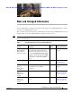
Se n d d o c u m e n t a t i o n c o m m e n t s t o m d s f e e d b a ck - d o c @ c i s c o . c o m New and Changed Information The Cisco MDS 9200 Series Hardware Installation Guide applies to Cisco MDS NX-OS Release 4.1(1b) and earlier Cisco MDS SAN-OS releases. Table 1 lists the new and changed features available with each supported Cisco MDS NX-OS release and SAN-OS release for the Cisco MDS 9500 Series, with the latest release first. Note As of NX-OS Release 4.
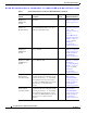
New and Changed Information Se n d d o c u m e n t a t i o n c o m m e n t s t o m d s f e e d b a ck - d o c @ c i s c o . c o m Table 1 Documented Features for the Cisco MDS 9200 Series (continued) Changed in Release Feature Description Where Documented 18/4-port Multiservice (MSM-18/4) module Added the Storage Media Encryption information. 3.2(1) The “1 8/4-Port Multiservice Module” section on page 1-21.
New and Changed Information Se n d d o c u m e n t a t i o n c o m m e n t s t o m d s f e e d b a ck - d o c @ c i s c o . c o m Table 1 Documented Features for the Cisco MDS 9200 Series (continued) Changed in Release Feature Description 12-port 4-Gbps Fibre Channel switching module 3.0(1) Added 12-port 4-Gbps Fibre Channel switching module. The switching module can be used in any of the Cisco MDS 9500 Series chassis and in the Cisco MDS 9216i and 9216A Switches.
New and Changed Information Se n d d o c u m e n t a t i o n c o m m e n t s t o m d s f e e d b a ck - d o c @ c i s c o .
Se n d d o c u m e n t a t i o n c o m m e n t s t o m d s f e e d b a ck - d o c @ c i s c o . c o m Preface This preface describes the audience, organization, and conventions of the Cisco MDS 9200 Series Hardware Installation Guide. It also provides information on how to obtain related documentation. Audience To use this installation guide, you must be familiar with electronic circuitry and wiring practices and preferably be an electronic or electromechanical technician.
Preface Se n d d o c u m e n t a t i o n c o m m e n t s t o m d s f e e d b a ck - d o c @ c i s c o . c o m Conventions This document uses the following conventions for notes, cautions, and safety warnings. Notes and Cautions contain important information that you should be aware of. Note Means reader take note. Notes contain helpful suggestions or references to material that are not covered in the publication. Caution Means reader be careful.
Preface Se n d d o c u m e n t a t i o n c o m m e n t s t o m d s f e e d b a ck - d o c @ c i s c o . c o m Warnung Dieses Warnsymbol bedeutet Gefahr. Sie befinden sich in einer Situation, die zu einer Körperverletzung führen könnte. Bevor Sie mit der Arbeit an irgendeinem Gerät beginnen, seien Sie sich der mit elektrischen Stromkreisen verbundenen Gefahren und der Standardpraktiken zur Vermeidung von Unfällen bewußt.
Preface Se n d d o c u m e n t a t i o n c o m m e n t s t o m d s f e e d b a ck - d o c @ c i s c o . c o m Related Documentation The documentation set for the Cisco MDS 9000 Family includes the following documents. The documentation set for the Cisco MDS 9000 Family includes the following documents. To find a document online, use the Cisco MDS NX-OS Documentation Locator at: http://www.cisco.com/en/US/products/ps5989/products_documentation_roadmap09186a00804500c1.html.
Preface Se n d d o c u m e n t a t i o n c o m m e n t s t o m d s f e e d b a ck - d o c @ c i s c o .
Preface Se n d d o c u m e n t a t i o n c o m m e n t s t o m d s f e e d b a ck - d o c @ c i s c o .
Se n d d o c u m e n t a t i o n c o m m e n t s t o m d s f e e d b a ck - d o c @ c i s c o . c o m CH A P T E R 1 Product Overview The Cisco MDS 9200 Series of multilayer modular fabric switches supports storage area network (SAN) applications. The Cisco MDS 9200 Series switches provide scalability, multitransport capability, security, and manageability to enterprise SANs.
Chapter 1 Product Overview Chassis Se n d d o c u m e n t a t i o n c o m m e n t s t o m d s f e e d b a ck - d o c @ c i s c o . c o m Note The Cisco MDS 9200 Series requires Cisco MDS SAN-OS Release 2.x, 3.x, and NX-OS 4.1(1b). The Cisco MDS 9222i Switch requires MDS SAN-OS Release 3.x and NX-OS 4.1(1b).
Chapter 1 Product Overview Chassis Se n d d o c u m e n t a t i o n c o m m e n t s t o m d s f e e d b a ck - d o c @ c i s c o . c o m The Cisco MDS 9216i (see Figure 1-2) has a nonremovable supervisor module (in slot 1) with an integrated 14-port Fibre Channel and 2-port Gigabit Ethernet switching module. See the “Cisco MDS 9216i Integrated Supervisor Module” section on page 1-6.
Chapter 1 Product Overview Chassis Se n d d o c u m e n t a t i o n c o m m e n t s t o m d s f e e d b a ck - d o c @ c i s c o .
Chapter 1 Product Overview Cisco MDS Fibre Channel Bladeswitch for IBM Blade Center Se n d d o c u m e n t a t i o n c o m m e n t s t o m d s f e e d b a ck - d o c @ c i s c o . c o m The Cisco MDS 9200 Series supports the following additional modules: • The nonremovable interface module (located above the integrated supervisor module), provides the console port (COM1 port) and the MGMT 10/100 Ethernet port for the integrated supervisor module. See the “Interface Modules” section on page 1-10.
Chapter 1 Product Overview Integrated Supervisor Modules Se n d d o c u m e n t a t i o n c o m m e n t s t o m d s f e e d b a ck - d o c @ c i s c o . c o m Cisco MDS 9222i Integrated Supervisor Module The nonremovable Cisco MDS 9222i integrated supervisor module provides the control and management functions of the Cisco MDS 9222i Switch, and it includes an integrated 18-port Fibre Channel switching and 4-port Gigabit Ethernet IP services module.
Chapter 1 Product Overview Integrated Supervisor Modules Se n d d o c u m e n t a t i o n c o m m e n t s t o m d s f e e d b a ck - d o c @ c i s c o . c o m Figure 1-5 shows the Cisco MDS 9216i integrated supervisor module with an integrated 14-port Fibre Channel and 2-port Gigabit Ethernet module.
Chapter 1 Product Overview Integrated Supervisor Modules Se n d d o c u m e n t a t i o n c o m m e n t s t o m d s f e e d b a ck - d o c @ c i s c o . c o m Figure 1-6 shows the Cisco MDS 9216A supervisor module with an integrated 16-port Switching module.
Chapter 1 Product Overview Integrated Supervisor Modules Se n d d o c u m e n t a t i o n c o m m e n t s t o m d s f e e d b a ck - d o c @ c i s c o . c o m LEDs on the Cisco MDS 9200 Series Integrated Supervisor Modules Table 1-1 describes the LEDs for the Cisco MDS 9200 Series integrated supervisor modules. Table 1-1 LEDs for the Cisco MDS 9200 Series Integrated Supervisor Modules LED Status Description Status Green All diagnostics pass.
Chapter 1 Product Overview Interface Modules Se n d d o c u m e n t a t i o n c o m m e n t s t o m d s f e e d b a ck - d o c @ c i s c o . c o m Interface Modules The nonremovable interface module is located above slot 1 (see Figure 1-7) and is identical for all Cisco MDS 9200 Series switches. It provides the following local and remote management interfaces: • RS-232 (EIA/TIA-232) console port with an RJ-45 connection that you can use to: – Configure the switch from the CLI.
Chapter 1 Product Overview Interface Modules Se n d d o c u m e n t a t i o n c o m m e n t s t o m d s f e e d b a ck - d o c @ c i s c o . c o m LEDs on the Interface Module Table 1-2 describes the LEDs for the Cisco MDS 9200 Series interface module. Table 1-2 LEDs on the Cisco MDS 9200 Series Interface Module LED Status Description Status Green All diagnostics pass. The module is operational (normal initialization sequence).
Chapter 1 Product Overview Cisco MDS 9000 Family Module Compatibility Se n d d o c u m e n t a t i o n c o m m e n t s t o m d s f e e d b a ck - d o c @ c i s c o . c o m Cisco MDS 9000 Family Module Compatibility Table 1-3 lists the hardware modules available and the chassis compatibility associated with them.
Chapter 1 Product Overview Switching Modules Se n d d o c u m e n t a t i o n c o m m e n t s t o m d s f e e d b a ck - d o c @ c i s c o . c o m – 32-Port 2-Gbps Fibre Channel Switching Module – 16-Port 2-Gbps Fibre Channel Switching Module The Cisco MDS 9200 Series supports one hot-swappable switching or services module in addition to the integrated module that is part of the supervisor module.
Chapter 1 Product Overview Switching Modules Se n d d o c u m e n t a t i o n c o m m e n t s t o m d s f e e d b a ck - d o c @ c i s c o . c o m 48-Port 4-Gbps Fibre Channel Switching Module 144474 Figure 1-9 Figure 1-10 shows the port numbering and LEDs on the 48-port 4-Gbps Fibre Channel switching module.
Chapter 1 Product Overview Switching Modules Se n d d o c u m e n t a t i o n c o m m e n t s t o m d s f e e d b a ck - d o c @ c i s c o . c o m Figure 1-11 24-Port 4-Gbps Fibre Channel Switching Module 3 144471 4 1 2 1 Status LED 3 Fibre Channel ports 2 Link LEDs 4 Port Group 12-Port 4-Gbps Fibre Channel Switching Module The 12-port 4-Gbps Fibre Channel switching module can be used in any of the Cisco MDS 9500 Series chassis and in the Cisco MDS 9216i and 9216A Switches.
Chapter 1 Product Overview Switching Modules Se n d d o c u m e n t a t i o n c o m m e n t s t o m d s f e e d b a ck - d o c @ c i s c o . c o m 4-Port 10-Gbps Fibre Channel Switching Module The 4-port 10-Gbps Fibre Channel switching module offers four dedicated bandwidth Fibre Channel ports running at 10 Gbps with no oversubscription. This module can be used in any of the Cisco MDS 9500 Series chassis and in the Cisco MDS 9216i and 9216A Switches.
Chapter 1 Product Overview Switching Modules Se n d d o c u m e n t a t i o n c o m m e n t s t o m d s f e e d b a ck - d o c @ c i s c o . c o m LEDs on the Generation 2 Switching Modules Table 1-4 describes the LEDs for the 48-port, 24-port, and 12-port 4-Gbps Fibre Channel Switching Modules and the 4-port 10-Gbps Fibre Channel Switching Module.
Chapter 1 Product Overview Switching Modules Se n d d o c u m e n t a t i o n c o m m e n t s t o m d s f e e d b a ck - d o c @ c i s c o . c o m Tip For a full 2-Gbps bandwidth between two hosts, connect one host to the first port group and the second host to the second port group.
Chapter 1 Product Overview Switching Modules Se n d d o c u m e n t a t i o n c o m m e n t s t o m d s f e e d b a ck - d o c @ c i s c o . c o m Switching Module Features Each switching module draws its power from the 42 V supplied on the backplane with local DC/DC power converters and regulators. The control processor on the switching module provides power-on, offline, and online diagnostics.
Chapter 1 Product Overview Switching Modules Se n d d o c u m e n t a t i o n c o m m e n t s t o m d s f e e d b a ck - d o c @ c i s c o . c o m LEDs on the Generation 1 Switching Module Table 1-5 describes the LEDs for the 16-port and 32-port switching modules. Table 1-5 LED LEDs for the Cisco MDS 9000 Family Generation 1 Fibre Channel Switching Modules Status Status Green Orange Red Speed Description All diagnostics pass. The module is operational (normal initialization sequence).
Chapter 1 Product Overview Services Modules Se n d d o c u m e n t a t i o n c o m m e n t s t o m d s f e e d b a ck - d o c @ c i s c o .
Chapter 1 Product Overview Services Modules Se n d d o c u m e n t a t i o n c o m m e n t s t o m d s f e e d b a ck - d o c @ c i s c o . c o m 18/4-Port Multiservice Federal Information Processing Standards Module The Cisco MDS 9000 Family 18/4-Port Multiservice Federal Information Processing Standards (MSFM-18/4) module is a FIPS 140-2 Level 3-compliant version of the MSM-18/4 module.
Chapter 1 Product Overview Services Modules Se n d d o c u m e n t a t i o n c o m m e n t s t o m d s f e e d b a ck - d o c @ c i s c o . c o m LEDs on the 18/4-Port Multiservice Module Table 1-6 describes the LEDs for the Cisco MDS 9000 Family 18/4-Port Multiservice module. Table 1-6 LED Status Status Green Orange Red Link LEDs for the Cisco MDS 9000 Family 18/4-Port Multiservice Modules Description All diagnostics pass. The module is operational (normal initialization sequence).
Chapter 1 Product Overview Services Modules Se n d d o c u m e n t a t i o n c o m m e n t s t o m d s f e e d b a ck - d o c @ c i s c o . c o m The MPS-14/2 modules support FCIP compression to maximize the effective WAN bandwidth of SAN extension solutions. It achieves up to a 30-to-1 compression ratio, with typical ratios of 2-to-1 over a wide variety of data sources.
Chapter 1 Product Overview Services Modules Se n d d o c u m e n t a t i o n c o m m e n t s t o m d s f e e d b a ck - d o c @ c i s c o . c o m LEDs on the 14/2-Port Multiprotocol Services Module Table 1-7 describes the LEDs for the MPS-14/2 modules. Table 1-7 LED Status Status Green Orange Red LEDs for the Cisco MDS 9000 Family MPS-14/2 Modules Description All diagnostics pass. The module is operational (normal initialization sequence).
Chapter 1 Product Overview Services Modules Se n d d o c u m e n t a t i o n c o m m e n t s t o m d s f e e d b a ck - d o c @ c i s c o . c o m The Fibre Channel port interfaces support hot-swappable Fibre Channel SFP transceivers, which can be short wavelength (SWL) for connectivity up to 1640 feet (500 meters), or long wavelength (LWL) for connectivity up to 6.2 miles (10 km).
Chapter 1 Product Overview Services Modules Se n d d o c u m e n t a t i o n c o m m e n t s t o m d s f e e d b a ck - d o c @ c i s c o . c o m LEDs on IP Storage Services Module Table 1-8 describes the LEDs for the IPS module. Table 1-8 LEDs for the Cisco MDS 9000 Family IPS Modules LED Status Description Status Green All diagnostics pass. The module is operational (normal initialization sequence).
Chapter 1 Product Overview Services Modules Se n d d o c u m e n t a t i o n c o m m e n t s t o m d s f e e d b a ck - d o c @ c i s c o . c o m The Fibre Channel ports support hot-swappable Fibre Channel SFP transceivers, which can be short wavelength (SWL) for connectivity up to 1050 feet (500 m), or long wavelength (LWL) for connectivity up to 6.2 miles (10 km). All interfaces are autosensing 1-Gbps or 2-Gbps compatible.
Chapter 1 Product Overview Services Modules Se n d d o c u m e n t a t i o n c o m m e n t s t o m d s f e e d b a ck - d o c @ c i s c o . c o m LEDs on the Storage Services Module Table 1-9 describes the LEDs for the Cisco MDS 9000 Family Storage Services Module. Table 1-9 LEDs for the Cisco MDS 9000 Family Storage Services Module LED Status Description Status Green All diagnostics pass. The module is operational (normal initialization sequence).
Chapter 1 Product Overview Services Modules Se n d d o c u m e n t a t i o n c o m m e n t s t o m d s f e e d b a ck - d o c @ c i s c o . c o m The Fibre Channel port interfaces support hot-swappable Fibre Channel SFP transceivers, which can be SWL for connectivity up to 1640 feet (500 meters), or LWL for connectivity up to 6.2 miles (10 km). All interfaces are autosensing 1-Gbps or 2-Gbps compatible.
Chapter 1 Product Overview Services Modules Se n d d o c u m e n t a t i o n c o m m e n t s t o m d s f e e d b a ck - d o c @ c i s c o . c o m LEDs on the Fibre Channel Advanced Services Module Table 1-10 describes the LEDs for the Cisco MDS 9000 Family ASM. Table 1-10 LEDs for the Cisco MDS 9000 Family ASM LED Status Description Status Green All diagnostics pass and the module is operational (normal initialization sequence).
Chapter 1 Product Overview Services Modules Se n d d o c u m e n t a t i o n c o m m e n t s t o m d s f e e d b a ck - d o c @ c i s c o . c o m The CSM shuts down if the software failure or an external power failure occurs, or if the module is separated from the backplane while it is still powered on. The CSM automatically backs up the data in memory to the disk drives and then shuts down. The CSM batteries provide adequate power to back up data without external power.
Chapter 1 Product Overview Services Modules Se n d d o c u m e n t a t i o n c o m m e n t s t o m d s f e e d b a ck - d o c @ c i s c o . c o m Figure 1-23 Cisco MDS 9000 Family CSM (Internal View) 4 2 3 94038 1 1 Disk drive 2 3 Battery 2 2 Disk drive 1 4 Battery 1 See the “Removing and Installing Switching and Services Modules” section on page 2-28 for information about removing and installing the CSM and maintaining the CSM batteries.
Chapter 1 Product Overview Services Modules Se n d d o c u m e n t a t i o n c o m m e n t s t o m d s f e e d b a ck - d o c @ c i s c o . c o m LEDs on the Caching Services Module Table 1-11 describes the LEDs for the CSM. Table 1-11 LEDs for the Cisco MDS 9000 Family CSM LED Status Description Status Green All diagnostics pass, and the module is operational (normal initialization sequence).
Chapter 1 Product Overview Power Supplies Se n d d o c u m e n t a t i o n c o m m e n t s t o m d s f e e d b a ck - d o c @ c i s c o . c o m Power Supplies The Cisco MDS 9200 Series supports dual hot-swappable 845-W AC power supplies, each of which can supply sufficient power to the entire chassis should one power supply fail. The power supplies monitor their output voltage and provide status to the supervisor module.
Chapter 1 Product Overview Fan Module Se n d d o c u m e n t a t i o n c o m m e n t s t o m d s f e e d b a ck - d o c @ c i s c o . c o m Fan Module The Cisco MDS 9200 Series supports a hot-swappable fan module with four fans. The fan module provides 80 cfm (cubic feet per minute) of cooling per slot, allowing 400 W of power dissipation per slot. Sensors on the supervisor module monitor the internal air temperature.
Chapter 1 Product Overview Supported Transceivers Se n d d o c u m e n t a t i o n c o m m e n t s t o m d s f e e d b a ck - d o c @ c i s c o . c o m For more information about the X2 transceiver, see the “X2 Transceiver Specifications” section on page B-7. For more information about a specific Cisco SFP transceiver, see the “SFP and SFP+ Transceiver Specifications” section on page B-10. SFP transceivers can be ordered separately or with the Cisco MDS 9200 Series.
Chapter 1 Product Overview Supported Transceivers Se n d d o c u m e n t a t i o n c o m m e n t s t o m d s f e e d b a ck - d o c @ c i s c o . c o m CWDM Combination Fibre Channel/Gigabit Ethernet SFP Transceivers All Fibre Channel and Gigabit Ethernet ports in the Cisco MDS 9200 Series support 1-Gbps/2-Gbps CWDM SFP transceivers. In addition, the Fibre Channel ports on Cisco MDS 9222i also support 4-Gbps CWDM SFP transceivers.
Se n d d o c u m e n t a t i o n c o m m e n t s t o m d s f e e d b a ck - d o c @ c i s c o .
Chapter 2 Installing the Cisco MDS 9200 Series Preinstallation Se n d d o c u m e n t a t i o n c o m m e n t s t o m d s f e e d b a ck - d o c @ c i s c o . c o m Warning A readily accessible two-poled disconnect device must be incorporated in the fixed wiring. Statement 1022 Note Each new switch requires a license. For information on licensing, see the Cisco MDS 9000 Family CLI Configuration Guide or the Cisco MDS 9000 Family Fabric Manager Configuration Guide.
Chapter 2 Installing the Cisco MDS 9200 Series Preinstallation Se n d d o c u m e n t a t i o n c o m m e n t s t o m d s f e e d b a ck - d o c @ c i s c o . c o m Installation Guidelines Follow these guidelines when installing the Cisco MDS 9200 Series: • Plan your site configuration and prepare the site before installing the chassis. Appendix D, “Site Planning and Maintenance Records,” lists the recommended site planning tasks.
Chapter 2 Installing the Cisco MDS 9200 Series Preinstallation Se n d d o c u m e n t a t i o n c o m m e n t s t o m d s f e e d b a ck - d o c @ c i s c o . c o m Required Equipment Before beginning the installation, ensure that the following items are ready: • Number 1 and number 2 Phillips screwdrivers with torque capability • 3/16-in.
Chapter 2 Installing the Cisco MDS 9200 Series Installing the Chassis in a Cabinet or Rack Se n d d o c u m e n t a t i o n c o m m e n t s t o m d s f e e d b a ck - d o c @ c i s c o . c o m Step 2 • Cables and connectors • Any optional items ordered Check for damage and report any discrepancies or damage to your customer service representative.
Chapter 2 Installing the Cisco MDS 9200 Series Installing the Chassis in a Cabinet or Rack Se n d d o c u m e n t a t i o n c o m m e n t s t o m d s f e e d b a ck - d o c @ c i s c o .
Chapter 2 Installing the Cisco MDS 9200 Series Installing the Chassis in a Cabinet or Rack Se n d d o c u m e n t a t i o n c o m m e n t s t o m d s f e e d b a ck - d o c @ c i s c o . c o m Step 2 Install the C brackets on the switch as follows: Position one of the C brackets against the side of the switch and align the screw holes as shown in Figure 2-2 and Figure 2-3. Then attach the bracket to the switch with two of the flat-head M4 screws. a.
Chapter 2 Installing the Cisco MDS 9200 Series Installing the Chassis in a Cabinet or Rack Se n d d o c u m e n t a t i o n c o m m e n t s t o m d s f e e d b a ck - d o c @ c i s c o .
Chapter 2 Installing the Cisco MDS 9200 Series Installing the Chassis in a Cabinet or Rack Se n d d o c u m e n t a t i o n c o m m e n t s t o m d s f e e d b a ck - d o c @ c i s c o . c o m Step 3 Position the chassis in the rack, inserting the rear of the chassis between the front mounting rails (see Figure 2-4). Use the 12-24 x 3/4-in. or 10-32 x 3/4-in. screws (depending on the type of rack) to attach the front rack-mount brackets to the mounting rails (three per side).
Chapter 2 Installing the Cisco MDS 9200 Series Installing the Chassis in a Cabinet or Rack Se n d d o c u m e n t a t i o n c o m m e n t s t o m d s f e e d b a ck - d o c @ c i s c o .
Chapter 2 Installing the Cisco MDS 9200 Series Installing the Switch in a Cabinet with Insufficient Front Clearance Se n d d o c u m e n t a t i o n c o m m e n t s t o m d s f e e d b a ck - d o c @ c i s c o . c o m Figure 2-6 shows the Cisco MDS 9200 Series completely installed in a rack.
Chapter 2 Installing the Cisco MDS 9200 Series Installing the Switch in a Cabinet with Insufficient Front Clearance Se n d d o c u m e n t a t i o n c o m m e n t s t o m d s f e e d b a ck - d o c @ c i s c o . c o m The rack-mount kit provided with the switch contains the items listed in Table 2-1. If you do not find all of the parts listed in Table 2-1, you may have an older version of the rack-mount kit, which only included the front rack-mount brackets.
Chapter 2 Installing the Cisco MDS 9200 Series Installing the Switch in a Cabinet with Insufficient Front Clearance Se n d d o c u m e n t a t i o n c o m m e n t s t o m d s f e e d b a ck - d o c @ c i s c o . c o m Step 2 Install the C brackets on the switch as follows: a. Position one of the C brackets against the side of the switch and align the screw holes as shown in Figure 2-8 and Figure 2-9. Then attach the bracket to the switch with two of the flat-head M4 screws.
Chapter 2 Installing the Cisco MDS 9200 Series Installing the Switch in a Cabinet with Insufficient Front Clearance Se n d d o c u m e n t a t i o n c o m m e n t s t o m d s f e e d b a ck - d o c @ c i s c o . c o m C Brackets for the Cisco MDS 9200 Series (Close-Up View) 94297 Figure 2-9 Note b.
Chapter 2 Installing the Cisco MDS 9200 Series Installing the Switch in a Cabinet with Insufficient Front Clearance Se n d d o c u m e n t a t i o n c o m m e n t s t o m d s f e e d b a ck - d o c @ c i s c o . c o m Figure 2-10 Front Rack-Mount Brackets (Rotated) Installed on the Cisco MDS 9200 Series MDS 9216i 1 2 3 4 5 6 7 8 GE1 9 11 GE2 LINK12 13 14 LINK- 116895 10 b. Step 2 Repeat with the other front rack-mount bracket on the other side of the switch.
Chapter 2 Installing the Cisco MDS 9200 Series Installing the Switch in a Cabinet with Insufficient Front Clearance Se n d d o c u m e n t a t i o n c o m m e n t s t o m d s f e e d b a ck - d o c @ c i s c o . c o m C Brackets for the Cisco MDS 9200 Series (Close-Up View) 94297 Figure 2-12 Note b.
Chapter 2 Installing the Cisco MDS 9200 Series Installing the Switch in a Cabinet with Insufficient Front Clearance Se n d d o c u m e n t a t i o n c o m m e n t s t o m d s f e e d b a ck - d o c @ c i s c o . c o m Note Figure 2-13 shows the front rack-mount brackets as rotated. Your chassis may have these brackets installed in the normal position.
Chapter 2 Installing the Cisco MDS 9200 Series Installing the Switch in a Cabinet with Insufficient Front Clearance Se n d d o c u m e n t a t i o n c o m m e n t s t o m d s f e e d b a ck - d o c @ c i s c o . c o m Figure 2-14 Inserting and Installing Slider Rails (Front View) Rear cabinet mounting rails Front cabinet mounting rails 3 113444 2 1 1 Screws, 12-24 or 10-32 2 Slider rail 3 C bracket Figure 2-15 shows the Cisco MDS 9200 Series completely installed in a rack.
Chapter 2 Installing the Cisco MDS 9200 Series System Grounding Se n d d o c u m e n t a t i o n c o m m e n t s t o m d s f e e d b a ck - d o c @ c i s c o .
Chapter 2 Installing the Cisco MDS 9200 Series System Grounding Se n d d o c u m e n t a t i o n c o m m e n t s t o m d s f e e d b a ck - d o c @ c i s c o . c o m Table 2-2 Grounding Best Practices Environment Commercial building is subjected to direct lightning strikes. Electromagnetic Noise Severity Level High All lightning protection devices must be installed in strict accordance with manufacturer recommendations.
Chapter 2 Installing the Cisco MDS 9200 Series System Grounding Se n d d o c u m e n t a t i o n c o m m e n t s t o m d s f e e d b a ck - d o c @ c i s c o . c o m Note In all situations, grounding practices must comply with local National Electric Code (NEC) requirements or local laws and regulations. Note Always ensure that all of the modules are completely installed and that the captive installation screws are fully tightened.
Chapter 2 Installing the Cisco MDS 9200 Series System Grounding Se n d d o c u m e n t a t i o n c o m m e n t s t o m d s f e e d b a ck - d o c @ c i s c o . c o m Step 2 Grasp the spring or alligator clip on the ESD wrist strap and momentarily touch the clip to a bare metal spot (unpainted surface) on the rack. Cisco recommends that you touch the clip to an unpainted rack rail so that any built-up static charge is then safely dissipated to the entire rack.
Chapter 2 Installing the Cisco MDS 9200 Series System Grounding Se n d d o c u m e n t a t i o n c o m m e n t s t o m d s f e e d b a ck - d o c @ c i s c o . c o m In addition, follow these guidelines when handling modules: Caution • Handle carriers by available handles or edges only; avoid touching the printed circuit boards or connectors. • Place a removed component board-side-up on an antistatic surface or in a static shielding container.
Chapter 2 Installing the Cisco MDS 9200 Series Grounding the Chassis Se n d d o c u m e n t a t i o n c o m m e n t s t o m d s f e e d b a ck - d o c @ c i s c o . c o m • Crimping tool to crimp the grounding wire to the grounding lug. • Wire-stripping tool to remove the insulation from the grounding wire. Grounding the Chassis The chassis has a grounding pad with two threaded M4 holes for attaching a grounding lug. Figure 2-17 shows the system ground location on the Cisco MDS 9200 Series.
Chapter 2 Installing the Cisco MDS 9200 Series Grounding the Chassis Se n d d o c u m e n t a t i o n c o m m e n t s t o m d s f e e d b a ck - d o c @ c i s c o .
Chapter 2 Installing the Cisco MDS 9200 Series Starting Up the Switch Se n d d o c u m e n t a t i o n c o m m e n t s t o m d s f e e d b a ck - d o c @ c i s c o . c o m To attach the grounding lug and cable to the chassis, follow these steps: Step 1 Use a wire-stripping tool to remove approximately 0.75 in. (19 mm) of the covering from the end of the grounding cable. Step 2 Insert the stripped end of the grounding cable into the open end of the grounding lug.
Chapter 2 Installing the Cisco MDS 9200 Series Starting Up the Switch Se n d d o c u m e n t a t i o n c o m m e n t s t o m d s f e e d b a ck - d o c @ c i s c o . c o m Step 2 Verify that both power supplies and the fan module are installed. Step 3 Verify that the power switches on both power supplies are off, and then plug the power cables into the power supplies and tighten the screws on the power cable retainers to ensure the cables cannot be pulled out.
Chapter 2 Installing the Cisco MDS 9200 Series Removing and Installing Components Se n d d o c u m e n t a t i o n c o m m e n t s t o m d s f e e d b a ck - d o c @ c i s c o . c o m Note If you purchased this product through a Cisco reseller, contact the reseller directly for technical support. If you purchased this product directly from Cisco, contact Cisco Technical Support at this URL: http://www.cisco.com/warp/public/687/Directory/DirTAC.shtml.
Chapter 2 Installing the Cisco MDS 9200 Series Removing and Installing Components Se n d d o c u m e n t a t i o n c o m m e n t s t o m d s f e e d b a ck - d o c @ c i s c o . c o m Warning Use of controls, adjustments, or performing procedures other than those specified may result in hazardous radiation exposure. Statement 1057 Warning Hazardous voltage or energy is present on the backplane when the system is operating. Use caution when servicing.
Chapter 2 Installing the Cisco MDS 9200 Series Removing and Installing Components Se n d d o c u m e n t a t i o n c o m m e n t s t o m d s f e e d b a ck - d o c @ c i s c o .
Chapter 2 Installing the Cisco MDS 9200 Series Removing and Installing Components Se n d d o c u m e n t a t i o n c o m m e n t s t o m d s f e e d b a ck - d o c @ c i s c o .
Chapter 2 Installing the Cisco MDS 9200 Series Removing and Installing Components Se n d d o c u m e n t a t i o n c o m m e n t s t o m d s f e e d b a ck - d o c @ c i s c o . c o m To remove a CSM module from the chassis, follow these steps: Step 1 Power off the module from the CLI. For information about the correct command to use, see the Cisco MDS 9000 Family CLI Configuration Guide. Step 2 Ensure that the backup process has completed by verifying that all LEDs on the module have turned off.
Chapter 2 Installing the Cisco MDS 9200 Series Removing and Installing Components Se n d d o c u m e n t a t i o n c o m m e n t s t o m d s f e e d b a ck - d o c @ c i s c o . c o m Warning Blank faceplates and cover panels serve three important functions: they prevent exposure to hazardous voltages and currents inside the chassis; they contain electromagnetic interference (EMI) that might disrupt other equipment; and they direct the flow of cooling air through the chassis.
Chapter 2 Installing the Cisco MDS 9200 Series Removing and Installing Components Se n d d o c u m e n t a t i o n c o m m e n t s t o m d s f e e d b a ck - d o c @ c i s c o .
Chapter 2 Installing the Cisco MDS 9200 Series Removing and Installing Components Se n d d o c u m e n t a t i o n c o m m e n t s t o m d s f e e d b a ck - d o c @ c i s c o . c o m Maintaining a Caching Services Module Caution Note Maintenance should only be performed by qualified service personnel. A minimum of two CSMs in each fabric are required for redundancy and data backup.
Chapter 2 Installing the Cisco MDS 9200 Series Removing and Installing Components Se n d d o c u m e n t a t i o n c o m m e n t s t o m d s f e e d b a ck - d o c @ c i s c o . c o m Removing and Installing Power Supplies The Cisco MDS 9200 Series supports dual 845-W AC power supplies that monitor output voltage and provide status to the supervisor module.
Chapter 2 Installing the Cisco MDS 9200 Series Removing and Installing Components Se n d d o c u m e n t a t i o n c o m m e n t s t o m d s f e e d b a ck - d o c @ c i s c o .
Chapter 2 Installing the Cisco MDS 9200 Series Removing and Installing Components Se n d d o c u m e n t a t i o n c o m m e n t s t o m d s f e e d b a ck - d o c @ c i s c o . c o m Caution In a system with dual power supplies, connect each power supply to a separate power source. In case of a power source failure, the second source will most likely still be available. Step 8 Turn the power switch to the on (|) position on the power supply.
Chapter 2 Installing the Cisco MDS 9200 Series Removing and Installing Components Se n d d o c u m e n t a t i o n c o m m e n t s t o m d s f e e d b a ck - d o c @ c i s c o . c o m Figure 2-23 shows a fan module partially installed in the Cisco MDS 9200 Series.
Chapter 2 Installing the Cisco MDS 9200 Series Removing and Installing Components Se n d d o c u m e n t a t i o n c o m m e n t s t o m d s f e e d b a ck - d o c @ c i s c o . c o m Step 3 Listen for the fans if the switch is powered on. You should immediately hear them operating. If you do not hear them, ensure that the fan module is inserted completely in the chassis and the faceplate is flush with the outside surface of the chassis. Step 4 Verify that the Fan Status LED is green.
Se n d d o c u m e n t a t i o n c o m m e n t s t o m d s f e e d b a ck - d o c @ c i s c o . c o m CH A P T E R 3 Connecting the Cisco MDS 9200 Series The Cisco MDS 9200 Series provides the following types of ports: Caution • Console port (interface module)—An RS-232 port that you can use to create a local management connection. • COM1 port (interface module)—An RS-232 port that you can use to connect to an external serial communication device such as a modem.
Chapter 3 Connecting the Cisco MDS 9200 Series Preparing for Network Connections Se n d d o c u m e n t a t i o n c o m m e n t s t o m d s f e e d b a ck - d o c @ c i s c o .
Chapter 3 Connecting the Cisco MDS 9200 Series Connecting to the Console Port Se n d d o c u m e n t a t i o n c o m m e n t s t o m d s f e e d b a ck - d o c @ c i s c o . c o m Note To connect the console port to a computer terminal, the computer must support VT100 terminal emulation. The terminal emulation software—frequently an application such as HyperTerminal or Procomm Plus—makes communication between the Cisco MDS 9200 Series and a computer possible during setup and configuration.
Chapter 3 Connecting the Cisco MDS 9200 Series Connecting to the COM1 Port Se n d d o c u m e n t a t i o n c o m m e n t s t o m d s f e e d b a ck - d o c @ c i s c o . c o m Connecting to the COM1 Port Note The COM1 port is not supported for connection to a console. The COM1 port (labeled COM1) is an RS-232 port with a DB-9 interface. (See Figure 3-2.) You can use this port to connect to an external serial communication device such as a modem.
Chapter 3 Connecting the Cisco MDS 9200 Series Connecting to the MGMT 10/100 Ethernet Port Se n d d o c u m e n t a t i o n c o m m e n t s t o m d s f e e d b a ck - d o c @ c i s c o .
Chapter 3 Connecting the Cisco MDS 9200 Series Connecting to a Fibre Channel Port Se n d d o c u m e n t a t i o n c o m m e n t s t o m d s f e e d b a ck - d o c @ c i s c o . c o m Connecting to a Fibre Channel Port The Fibre Channel ports on the switch modules are compatible with LC-type fiber-optic SFP transceivers and cables. You can use the Fibre Channel ports to connect to the SAN or for in-band management.
Chapter 3 Connecting the Cisco MDS 9200 Series Connecting to a Fibre Channel Port Se n d d o c u m e n t a t i o n c o m m e n t s t o m d s f e e d b a ck - d o c @ c i s c o . c o m The Cisco MDS 9000 Family supports X2 transceivers with SC connectors. (See Figure 3-4.
Chapter 3 Connecting the Cisco MDS 9200 Series Connecting to a Fibre Channel Port Se n d d o c u m e n t a t i o n c o m m e n t s t o m d s f e e d b a ck - d o c @ c i s c o . c o m Installing an X2 Transceiver To install an X2 transceiver, follow these steps: Step 1 Attach an ESD-preventive wrist strap and follow its instructions for use. Caution If the transceiver does not install easily, ensure that it is correctly oriented before continuing.
Chapter 3 Connecting the Cisco MDS 9200 Series Connecting to a Fibre Channel Port Se n d d o c u m e n t a t i o n c o m m e n t s t o m d s f e e d b a ck - d o c @ c i s c o . c o m Note Use only Cisco SFP transceivers on the Cisco MDS 9200 Series. Each Cisco SFP transceiver is encoded with model information that enables the switch to verify that the SFP transceiver meets the requirements for the switch.
Chapter 3 Connecting the Cisco MDS 9200 Series Connecting to a Fibre Channel Port Se n d d o c u m e n t a t i o n c o m m e n t s t o m d s f e e d b a ck - d o c @ c i s c o . c o m If you cannot install the cable into the transceiver, insert or leave the dust plug in the cable end of the transceiver. Note Removing an SFP Transceiver To remove an SFP transceiver, follow these steps: Step 1 Attach an ESD-preventive wrist strap and follow its instructions for use.
Chapter 3 Connecting the Cisco MDS 9200 Series Connecting to a Fibre Channel Port Se n d d o c u m e n t a t i o n c o m m e n t s t o m d s f e e d b a ck - d o c @ c i s c o . c o m Alternate Removal Method for Bale Clasp SFP Transceivers 115237 Figure 3-7 Step 4 Insert a dust cover into the port end of the transceiver and place the transceiver on an antistatic mat or into a static shielding bag if you plan to return it to the factory.
Chapter 3 Connecting the Cisco MDS 9200 Series Connecting to a Fibre Channel Port Se n d d o c u m e n t a t i o n c o m m e n t s t o m d s f e e d b a ck - d o c @ c i s c o . c o m Figure 3-8 Connecting the LC-Type Cable to a Fibre Channel Port LC plug 91681 SFP module Caution If the cable does not install easily, ensure that it is correctly oriented before continuing.
Chapter 3 Connecting the Cisco MDS 9200 Series Connecting to a Fibre Channel Port Se n d d o c u m e n t a t i o n c o m m e n t s t o m d s f e e d b a ck - d o c @ c i s c o . c o m Maintaining SFP Transceivers and Fiber-Optic Cables SFP transceivers and fiber-optic cables must be kept clean and dust-free to maintain high signal accuracy and prevent damage to the connectors. Attenuation (Loss of Light) is increased by contamination and should be below 0.35 dB.
Chapter 3 Connecting the Cisco MDS 9200 Series Connecting to a Fibre Channel Port Se n d d o c u m e n t a t i o n c o m m e n t s t o m d s f e e d b a ck - d o c @ c i s c o .
Se n d d o c u m e n t a t i o n c o m m e n t s t o m d s f e e d b a ck - d o c @ c i s c o .
Appendix A Cabinet and Rack Installation Cabinet and Rack Requirements Se n d d o c u m e n t a t i o n c o m m e n t s t o m d s f e e d b a ck - d o c @ c i s c o . c o m The cabinet or rack must also meet the following requirements: • The minimum vertical rack space per chassis must be three RU (rack units), equal to 5.25 in. (13.3 cm). • The width between the rack-mounting rails must be at least 17.75 in. (45.1 cm) if the rear of the switch is not attached to the rack.
Appendix A Cabinet and Rack Installation Cabinet and Rack Requirements Se n d d o c u m e n t a t i o n c o m m e n t s t o m d s f e e d b a ck - d o c @ c i s c o . c o m Requirements Specific to Solid-Walled Cabinets A solid-walled cabinet is defined here as a cabinet with solid front and rear doors and solid side walls.
Appendix A Cabinet and Rack Installation Cisco MDS 9000 Family telco and EIA Shelf Bracket Se n d d o c u m e n t a t i o n c o m m e n t s t o m d s f e e d b a ck - d o c @ c i s c o . c o m Cisco MDS 9000 Family telco and EIA Shelf Bracket The optional telco and EIA Shelf Bracket Kit (part number DS-SHELF=) can temporarily or permanently support the Cisco MDS 9200 Series during installation.
Appendix A Cabinet and Rack Installation Cisco MDS 9000 Family telco and EIA Shelf Bracket Se n d d o c u m e n t a t i o n c o m m e n t s t o m d s f e e d b a ck - d o c @ c i s c o . c o m • The rack has sufficient vertical clearance for the chassis plus 2 RU for the shelf brackets, and any desired clearance for the installation process.
Appendix A Cabinet and Rack Installation Cisco MDS 9000 Family telco and EIA Shelf Bracket Se n d d o c u m e n t a t i o n c o m m e n t s t o m d s f e e d b a ck - d o c @ c i s c o . c o m Installing the Shelf Bracket Kit into a Two-Post telco Rack Figure A-1 shows the installation of the shelf bracket kit into a two-post telco rack.
Appendix A Cabinet and Rack Installation Cisco MDS 9000 Family telco and EIA Shelf Bracket Se n d d o c u m e n t a t i o n c o m m e n t s t o m d s f e e d b a ck - d o c @ c i s c o . c o m Installing the Shelf Bracket Kit into a Four-Post EIA Rack Figure A-2 shows the installation of the shelf bracket kit into a four-post EIA rack.
Appendix A Cabinet and Rack Installation Cisco MDS 9000 Family telco and EIA Shelf Bracket Se n d d o c u m e n t a t i o n c o m m e n t s t o m d s f e e d b a ck - d o c @ c i s c o . c o m Step 4 Attach the crossbar to the shelf brackets as shown in Figure A-2, using the 10-32 screws. Step 5 Insert the slider rails into the shelf brackets as shown in Figure A-2. Then, attach them to the rear rack-mounting rails using a minimum of four 12-24 or 10-24 screws.
Appendix A Cabinet and Rack Installation Cisco MDS 9000 Family telco and EIA Shelf Bracket Se n d d o c u m e n t a t i o n c o m m e n t s t o m d s f e e d b a ck - d o c @ c i s c o . c o m Removing the Shelf Bracket Kit (Optional) The shelf bracket kit can be removed once the Cisco MDS 9200 Series has been installed in a two-post telco or four-post EIA rack, and the front rack-mount brackets are securely attached to the rack-mounting rails.
Appendix A Cabinet and Rack Installation Cisco MDS 9000 Family telco and EIA Shelf Bracket Se n d d o c u m e n t a t i o n c o m m e n t s t o m d s f e e d b a ck - d o c @ c i s c o .
Se n d d o c u m e n t a t i o n c o m m e n t s t o m d s f e e d b a ck - d o c @ c i s c o . c o m A P P E N D I X B Technical Specifications This appendix includes the following sections: Note • Switch Specifications, page B-1 • Module Specifications, page B-2 • Power Specifications, page B-4 • X2 Transceiver Specifications, page B-7 • SFP and SFP+ Transceiver Specifications, page B-10 Specifications for cables and connectors are provided in Appendix C, “Cable and Port Specifications.
Appendix B Technical Specifications Module Specifications Se n d d o c u m e n t a t i o n c o m m e n t s t o m d s f e e d b a ck - d o c @ c i s c o . c o m Table B-2 lists the physical specifications for the Cisco MDS 9200 Series. Table B-2 Physical Specifications for the Cisco MDS 9200 Series Description Specification Dimensions (HxWxD) 5.25 x 17.5 x 22.75 in. (13.3 x 44.5 x 57.8 cm) Chassis requires 3 RU1. Chassis depth including cable guide is 27.75 in. (70.3 cm).
Appendix B Technical Specifications Module Specifications Se n d d o c u m e n t a t i o n c o m m e n t s t o m d s f e e d b a ck - d o c @ c i s c o . c o m Table B-3 Cisco MDS 9200 Series Module Specifications (continued) Description Specification Altitude, designed and tested for operation -200 to 10000 ft (-60 to 3000 m) Physical Characteristics Dimensions 1.75 x15.5 x16.5 in. (4.4 x 39.4 x 41.
Appendix B Technical Specifications Power Specifications Se n d d o c u m e n t a t i o n c o m m e n t s t o m d s f e e d b a ck - d o c @ c i s c o . c o m Table B-5 Weight of Modules in the Cisco MDS 9000 Family (continued) Module Weight SSM 11 lb (5 kg) CSM 11.5 lb (5.2 kg) ASM 11 lb (5 kg) IPS-8 10 lb (4.5 kg) IPS-4 9 lb (4.1 kg) MSM-18/4 8.5 lb (3.86 kg) MSFM-18/4 8.5 lb (3.86 kg) MPS-14/2 10 lb (4.5 kg) Supervisor-2 for MDS 9500 Series 7.
Appendix B Technical Specifications Power Specifications Se n d d o c u m e n t a t i o n c o m m e n t s t o m d s f e e d b a ck - d o c @ c i s c o . c o m Component Power Requirements and Heat Dissipation Specifications Consider heat dissipation when sizing the air-conditioning requirements for an installation.
Appendix B Technical Specifications Power Specifications Se n d d o c u m e n t a t i o n c o m m e n t s t o m d s f e e d b a ck - d o c @ c i s c o . c o m Table B-7 Power Requirements and Heat Dissipation for the 845-W Power Supply (continued) SAN-OS Release Input Current Power Heat Required Dissipation 90 VAC 120 VAC (watts) (BTU/hr) (amps) (amps) 180 VAC (amps) 240 VAC (amps) 24-port 4-Gbps switching module, DS-X9124 3.x 147 628 2.04 1.53 1.02 0.77 2.x and 1.
Appendix B Technical Specifications X2 Transceiver Specifications Se n d d o c u m e n t a t i o n c o m m e n t s t o m d s f e e d b a ck - d o c @ c i s c o . c o m X2 Transceiver Specifications The Cisco MDS 9200 Series is compatible with X2 transceivers and cables that have SC connectors. Each transceiver must match the transceiver on the other end of the cable in terms of wavelength, and the cable must not exceed the stipulated cable length for reliable communications.
Appendix B Technical Specifications General Specification for Cisco 10-Gbps Fibre Channel X2 Transceivers Se n d d o c u m e n t a t i o n c o m m e n t s t o m d s f e e d b a ck - d o c @ c i s c o . c o m Environmental Conditions and Power Requirement Specifications for Cisco 10-Gbps Fibre Channel X2 Transceivers Table B-10 provides the power requirement specifications for Cisco 10-Gbps Fibre Channel X2 transceivers.
Appendix B Technical Specifications General Specification for Cisco 10-Gbps Fibre Channel X2 Transceivers Se n d d o c u m e n t a t i o n c o m m e n t s t o m d s f e e d b a ck - d o c @ c i s c o . c o m General Specification for Cisco 10-Gbps Ethernet X2 Transceivers Table B-13 provides the general specifications for Cisco 10-Gbps Ethernet X2 transceivers.
Appendix B Technical Specifications SFP and SFP+ Transceiver Specifications Se n d d o c u m e n t a t i o n c o m m e n t s t o m d s f e e d b a ck - d o c @ c i s c o . c o m • Support for 32 nontunable ITU 100-GHz wavelengths compatible with the Cisco ONS DWDM channel plan. • Support for digital optical monitoring capability. For more information, refer to the data sheet at: http://www.cisco.com/en/US/products/ps6576/index.
Appendix B Technical Specifications SFP and SFP+ Transceiver Specifications Se n d d o c u m e n t a t i o n c o m m e n t s t o m d s f e e d b a ck - d o c @ c i s c o . c o m General Specifications for Cisco 8-Gbps Fibre Channel SFP+ Transceivers Table B-17 provides the general specifications for Cisco Fibre Channel SFP+ transceivers.
Appendix B Technical Specifications SFP and SFP+ Transceiver Specifications Se n d d o c u m e n t a t i o n c o m m e n t s t o m d s f e e d b a ck - d o c @ c i s c o . c o m Table B-18 Power Requirements Specification for Cisco 8-Gbps Fibre Channel SFP+ Transceivers (continued) SFP Average Transmit Power (dBm) Average Receive Power (dBm) Maximum Maximum Minimum –11.7 (2 Gbps) –3 (2 Gbps) –1 (4 Gbps) –8.4 (4 Gbps) –1 (4 Gbps) +0.5 (8 Gbps) –8.4 (8 Gbps) +0.
Appendix B Technical Specifications SFP and SFP+ Transceiver Specifications Se n d d o c u m e n t a t i o n c o m m e n t s t o m d s f e e d b a ck - d o c @ c i s c o . c o m General Specifications for Cisco 4-Gbps Fibre Channel SFP Transceivers Table B-20 provides the general specifications for Cisco Fibre Channel SFP transceivers.
Appendix B Technical Specifications SFP and SFP+ Transceiver Specifications Se n d d o c u m e n t a t i o n c o m m e n t s t o m d s f e e d b a ck - d o c @ c i s c o . c o m Table B-22 provides the environment specification for the Cisco 4-Gbps Fibre Channel SFP transceivers.
Appendix B Technical Specifications SFP and SFP+ Transceiver Specifications Se n d d o c u m e n t a t i o n c o m m e n t s t o m d s f e e d b a ck - d o c @ c i s c o . c o m Table B-25 provides the environmental specification for Cisco 2-Gbps Fibre Channel SFP transceivers.
Appendix B Technical Specifications SFP and SFP+ Transceiver Specifications Se n d d o c u m e n t a t i o n c o m m e n t s t o m d s f e e d b a ck - d o c @ c i s c o . c o m General Specifications for Cisco Fibre Channel/Gigabit Ethernet SFP Transceivers Table B-28 provides general specification for Cisco Fibre Channel/Gigabit Ethernet SFP transceiver.
Appendix B Technical Specifications SFP and SFP+ Transceiver Specifications Se n d d o c u m e n t a t i o n c o m m e n t s t o m d s f e e d b a ck - d o c @ c i s c o . c o m Table B-30 provides the environmental specification for Cisco Fibre Channel/Gigabit Ethernet SFP transceivers.
Appendix B Technical Specifications SFP and SFP+ Transceiver Specifications Se n d d o c u m e n t a t i o n c o m m e n t s t o m d s f e e d b a ck - d o c @ c i s c o . c o m Table B-32 lists the Cisco 4-Gbps CWDM SFP transceivers available through Cisco.
Appendix B Technical Specifications SFP and SFP+ Transceiver Specifications Se n d d o c u m e n t a t i o n c o m m e n t s t o m d s f e e d b a ck - d o c @ c i s c o . c o m Table B-34 Note Optical Specification for Cisco 2-Gbps CWDM SFP Transceivers (continued) Parameters Symbol Minimum Typical Maximum Units Notes/Conditions Receiver Optical Input Power (BER <10-12 with PRBS 2-7-1) Pin -29.0 – -7.0 dBm At 1.
Appendix B Technical Specifications SFP and SFP+ Transceiver Specifications Se n d d o c u m e n t a t i o n c o m m e n t s t o m d s f e e d b a ck - d o c @ c i s c o . c o m Table B-36 provides the optical specifications for Cisco 4-Gbps CWDM SFP transceivers.
Appendix B Technical Specifications SFP and SFP+ Transceiver Specifications Se n d d o c u m e n t a t i o n c o m m e n t s t o m d s f e e d b a ck - d o c @ c i s c o . c o m Cisco Gigabit Ethernet Transceivers Cisco Systems provides a 1-Gbps Gigabit Ethernet SFP transceiver used on the Cisco MDS 9000 IPS modules. Table B-37 lists the transceiver supported on the Cisco MDS 9216.
Appendix B Technical Specifications SFP and SFP+ Transceiver Specifications Se n d d o c u m e n t a t i o n c o m m e n t s t o m d s f e e d b a ck - d o c @ c i s c o . c o m DWDM SFP Transceivers The Cisco 2-Gbps DWDM SFP modules enable enterprises and service providers to provide scalable, easy-to-deploy DWDM Fibre Channel services in their networks. The main features of the Cisco DWDM SFP include: Note • Support for International Telecommunication Union (ITU) 100-GHz wavelength grid.
Se n d d o c u m e n t a t i o n c o m m e n t s t o m d s f e e d b a ck - d o c @ c i s c o .
Appendix C Cable and Port Specifications Console Port Se n d d o c u m e n t a t i o n c o m m e n t s t o m d s f e e d b a ck - d o c @ c i s c o . c o m Console Port The console port is an asynchronous RS-232 serial port with an RJ-45 connector. You can use the RJ-45 rollover cable and the RJ-45/DSUB F/F adapter or the DB-9F/RJ-45F PC terminal adapter to connect the console port to a computer running terminal emulation software.
Appendix C Cable and Port Specifications COM1 Port Se n d d o c u m e n t a t i o n c o m m e n t s t o m d s f e e d b a ck - d o c @ c i s c o . c o m Connecting the Console Port to a Computer Using the DB-9 Adapter You can use the RJ-45 rollover cable and DB-9F/RJ-45F PC terminal (labeled “Terminal”) to connect the console port to a computer running terminal emulation software. Table C-3 lists the pinouts for the console port, the RJ-45 rollover cable, and the DB-9F/RJ-45F PC terminal.
Appendix C Cable and Port Specifications MGMT 10/100/1000 Ethernet Port Se n d d o c u m e n t a t i o n c o m m e n t s t o m d s f e e d b a ck - d o c @ c i s c o . c o m Table C-4 COM1 Port Pinouts (continued) Pin Signal 8 CTS 9 RI Connecting the COM1 Port to a Modem You can use the DB-9F/RJ-45F PC terminal (labeled “Terminal”) to connect to the COM1 port, and the RJ-45/DSUB R/P adapter (labeled “Modem”) to connect to the modem. You can use the RJ-45 rollover cable to connect these adapters.
Appendix C Cable and Port Specifications MGMT 10/100/1000 Ethernet Port Se n d d o c u m e n t a t i o n c o m m e n t s t o m d s f e e d b a ck - d o c @ c i s c o . c o m Table C-6 lists the connector pinouts and signal names for a 10/100/1000BASE-T management port (MDI) cable. Note The RJ-45 interface only uses pins 1, 2, 3, and 6.
Appendix C Cable and Port Specifications MGMT 10/100 Ethernet Port Se n d d o c u m e n t a t i o n c o m m e n t s t o m d s f e e d b a ck - d o c @ c i s c o . c o m MGMT 10/100 Ethernet Port The MGMT 10/100 Ethernet port is an Ethernet port with an RJ-45 connector. You can use a modular, RJ-45, straight-through UTP cable to connect the management port to an external hub, switch, or router (see Figure C-3).
Appendix C Cable and Port Specifications MGMT 10/100 Ethernet Port Se n d d o c u m e n t a t i o n c o m m e n t s t o m d s f e e d b a ck - d o c @ c i s c o . c o m Figure C-4 shows a schematic of the 10/100BASE-T cable required to connect the management port to a switch or hub (not provided with the switch).
Appendix C Cable and Port Specifications MGMT 10/100 Ethernet Port Se n d d o c u m e n t a t i o n c o m m e n t s t o m d s f e e d b a ck - d o c @ c i s c o . c o m Table C-8 Power Cords for the MDS 9200, 9100, and 9020 Series of Switches (continued) Length Description Feet Meters Power Cord, 250 VAC 10 A CEI 23-16/VII Plug, Italy 8.2 2.5 Power Cord, 250 VAC 10 A BS1363 Plug (13 A fuse), 8.2 UK 2.5 Power Cord, 250 VAC 10 A IRAM 2073 Plug, Argentina 8.2 2.
Appendix C Cable and Port Specifications MGMT 10/100 Ethernet Port Se n d d o c u m e n t a t i o n c o m m e n t s t o m d s f e e d b a ck - d o c @ c i s c o .
Appendix C Cable and Port Specifications MGMT 10/100 Ethernet Port Se n d d o c u m e n t a t i o n c o m m e n t s t o m d s f e e d b a ck - d o c @ c i s c o . c o m Figure C-7 shows an additional plug that is supported for the 3000-W and 2500-W power supply, using 110 VAC. Note Using the plug in Figure C-7 at 110 VAC results in 1300 W available to the system.
Appendix C Cable and Port Specifications MGMT 10/100 Ethernet Port Se n d d o c u m e n t a t i o n c o m m e n t s t o m d s f e e d b a ck - d o c @ c i s c o . c o m Jumper Power Cord Figure C-9 shows the C19 and C20 connectors on the optional jumper power cord for the Cisco MDS 9200 Series. The C19 connector plugs into the C20 inlet on the Cisco MDS 9200 Series power supply, while the C20 connector plugs into the C19 receptacle of a power distribution unit for a cabinet.
Appendix C Cable and Port Specifications MGMT 10/100 Ethernet Port Se n d d o c u m e n t a t i o n c o m m e n t s t o m d s f e e d b a ck - d o c @ c i s c o .
Se n d d o c u m e n t a t i o n c o m m e n t s t o m d s f e e d b a ck - d o c @ c i s c o .
Appendix D Site Planning and Maintenance Records Site Preparation Checklist Se n d d o c u m e n t a t i o n c o m m e n t s t o m d s f e e d b a ck - d o c @ c i s c o . c o m Table D-1 Site Planning Checklist Task No.
Appendix D Site Planning and Maintenance Records Contact and Site Information Se n d d o c u m e n t a t i o n c o m m e n t s t o m d s f e e d b a ck - d o c @ c i s c o . c o m 3. EMI = electromagnetic interference. 4. RFI = radio frequency interference. Contact and Site Information Use the following worksheet (Table D-2) to record contact and site information.
Appendix D Site Planning and Maintenance Records Chassis and Module Information Se n d d o c u m e n t a t i o n c o m m e n t s t o m d s f e e d b a ck - d o c @ c i s c o . c o m Chassis and Module Information Use the following worksheets (Table D-3 and Table D-4) to record information about the chassis and modules.
Se n d d o c u m e n t a t i o n c o m m e n t s t o m d s f e e d b a ck - d o c @ c i s c o .
Index Se n d d o c u m e n t a t i o n c o m m e n t s t o m d s f e e d b a ck - d o c @ c i s c o . c o m cabling battery specifications (table) COM1 port description C-3 console port figure C-2 MGMT 10/100/1000 Ethernet port MGMT 10/100 Ethernet port requirements C-4 C-6 SFP transceivers 1-31 1-32 installing (procedure) 2-33 internal view (figure) 1-32 LEDs (table) 3-1 maintaining 3-11, 3-12 1-34 2-35 Caching Services Module.
Index Se n d d o c u m e n t a t i o n c o m m e n t s t o m d s f e e d b a ck - d o c @ c i s c o .
Index Se n d d o c u m e n t a t i o n c o m m e n t s t o m d s f e e d b a ck - d o c @ c i s c o .
Index Se n d d o c u m e n t a t i o n c o m m e n t s t o m d s f e e d b a ck - d o c @ c i s c o .
Index Se n d d o c u m e n t a t i o n c o m m e n t s t o m d s f e e d b a ck - d o c @ c i s c o .