CHAPT ER 2 Hardware Installation This chapter provides procedures for installing a LightStream 2020 multiservice ATM switch (LS2020 switch) in a networking environment.
Installing an LS2020 Switch in Rack Step 5 Inspect all external surfaces of the chassis for signs of damage. Pay special attention to areas of the chassis corresponding to visible damage to the shipping container. Step 6 Document any damage noted during the inspection. Step 7 Contact your LS2020 vendor if your LS2020 switch has been damaged during shipment. Installing an LS2020 Switch in Rack This section explains how to mount an LS2020 chassis in an equipment rack.
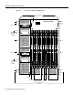
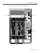
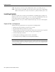
Installing an LS2020 Switch in Rack Step 3 Remove the following chassis components to reduce the weight of the system during installation. • • Blowers (top front and top rear) Power supplies (right rear) These components are located behind removable covers. Figure 2-1 shows the front view of the LS2020 chassis, while Figure 2-2 shows the rear view of the chassis.
Installing an LS2020 Switch in Rack Figure 2-1 Front View of LightStream 2020 Chassis Mounting flanges Blower (behind cover) LightStream 2020 ™ Disk assembly Disk assembly handle unsafe for lifting! Disk assembly H4812 Disk assembly handle unsafe for lifting! ESD jack NP card Line cards Switch cards Slots for mounting screws (12 places) 2-4 LightStream 2020 Installation Guide Line cards
R F H4811 R F CEMAC RX TX O O A TX0 RX TX RX 1 RX1 O A TX1 O A 2 RX2 RX TX5 RX6 TX6 RX7 T1 I/O access cards Consulter le manuel d'installation au sujet de l'avertissement sur le laser. O A TX2 TX 3 RX3 TX3 Warnhinweise fur den Gebrauch des Lasers sind im Installationshandbuch enthalten. R F WAVELENGTH: 850nm MAXIMUM OUTPUT: 63.1 µW CERTIFIED TO: EN 60 825:1994 R F 0 2 4 6 THIS APERTURE. DO NOT STARE INTO BEAM OR VIEW DIRECTLY WITH OPTICAL INSTRUMENTS. CLASS 3A LASER PRODUCT.
Wiring a DC-Powered System Wiring a DC-Powered System The procedure in this section explains how to wire a DC-powered LS2020 switch to a DC power source. This task should be performed only by qualified service personnel or a licensed electrician. This section applies only to systems with the DC power option. If you have a standard AC-powered system, skip to the section “Installing Fantails.
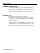
Wiring a DC-Powered System Figure 2-3 Connections to DC-powered Chassis Terminal block for alarm circuit Removable cover Terminal block for system power H3690 Circuit breaker/ power switch Wiring Procedure Warning The wiring task should be performed only by a licensed electrician or qualified service personnel. Untrained personnel may be exposed to hazardous DC voltages.
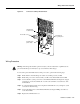
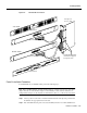
Installing Fantails Step 7 Repeat the procedure above if the LS2020 switch contains a second DC power tray. Step 8 Observe the green power LED on the front of the power tray when power is applied. If the LED is not lit, check for incorrectly connected wires or problems in the DC power source. Installing Fantails This section explains how to mount and connect fantails in your LS2020 switch (see Figure 2-4). Fantails provide connectors for data cables on low-speed (V.35, X.
Installing Fantails Figure 2-4 Fantail Cable Connections Low-speed access card V.35 fantail Front view H3691 Rear view RS-449 fantail Rear view 100-pin high-density connectors support four ports each Front view Fantail Installation Procedure To install fantails in your LS2020 switch, perform the following steps: Note Before installing fantails, check the interface jumpers on each low-speed access card. These jumpers must be set to the interface displayed on the fantail(s) for that card.
Connecting Cables Step 3 Attach the fantail cable(s) to the back of the fantail and the corresponding access card in the chassis. (Performing this task now is recommended, rather than installing the fantail first and having to reach behind it to attach the cable(s) to a connector that you cannot observe directly.) Note that the cable is reversible; that is, either end of the cable can be connected to the fantail. Exercise care to avoid suspending the weight of the fantail on the cable.
Closing the Chassis Note For ease of maintenance, route cables at the back of the LS2020 chassis in a way that enables you to later remove any access card without disconnecting cables attached to other access cards or fantails. Closing the Chassis Before applying system power, check the front and back of the system to ensure that all boards, disks, blowers, bulkheads, filler panels, and covers are in place and secured firmly to the chassis frame.
Applying System Power Figure 2-5 LightStream 2020 AC and DC Power Trays Power switch Terminal block Power inlet Power switch Power switch Terminal block Chassis with DC power trays H3671 Power switch Power inlet Chassis with AC power trays Note When the LS2020 switch is powered up, the blowers start running and the test and control system (TCS) applies power to the cards and initiates the power-on self test (POST) sequence.
Installing Modems Figure 2-6 LightStream 2020 Power-up Sequence Green LED on power supply lights up TCS powers up; LEDs on each card light up TCS slaves enable power on cards; VCC LEDs light up to indicate local power on each card Blowers start running Switch cards arbitrate ~5 seconds to select master POST executes; yellow FLT LED lights up; green RDY LEDs blink on each card while POST runs POST passes ? Yellow FLT LED lights up; green RDY LED goes out Yellow FLT LED goes out; green RDY LED ligh
Basic LS2020 Configuration Tasks A modem attached to an LS2020 node must be a V.42 Hayes-compatible unit capable of operating at 2400 baud. The following modems are compatible with the LS2020 switch: • • • Zoom 9624V Zoom FXV (FXV9624V) Hayes SmartModem 2400 V.24 For information on the default modem port settings and how to change them, see the LightStream 2020 Network Operations Guide.
Basic LS2020 Configuration Tasks Host Name You must assign a unique host name to each LS2020 node. Typically, a name can be chosen to reflect the node’s geographic location (for example, Tokyo2) or its function within an organization (for example, mfg3). The name may consist of any combination of letters and numbers up to 32 characters, but it must not begin with a number. Thus, Pensacola23 is a valid host name, but 23Pensacola is not; similarly, Pensacola.
Basic LS2020 Configuration Tasks • Subnet mask for the NP’s Ethernet address The subnet mask for the NP’s Ethernet address specifies which portion of the IP address is the network number and which portion is the host ID. This mask is the same for all nodes on the Ethernet LAN attached to the primary NP. You can obtain the subnet mask from the Ethernet LAN administrator.
Basic LS2020 Configuration Tasks For more information about trunk port configuration, refer to the LightStream 2020 Configuration Guide. Attaching a Terminal to a Console Port This section explains how to attach a VT100 terminal (or equivalent) to the console port of a Release 2 switch card and how to match the baud rate between them. Background Information Prior to Release 2.
Basic LS2020 Configuration Tasks TCS hub<> set baudrate where: TCS hub<> Is the TCS hub prompt for the switch card (either switch card A or B, as appropriate) set Is the command that operates in conjunction with command arguments to set the baud rate for the specified switch and the specified port Denotes that the set command is to apply to switch card A or B, whichever is specified Denotes that the set command is to app
Basic LS2020 Configuration Tasks • Method 2, changing modem baud rate through use of redundant components—With this method, the assumption is made that the local console terminal is not available (for example, if a software installation or upgrade is being done remotely). The assumption is also made that your LS2020 chassis is equipped with redundant Release 2 switch cards and modems, and that you have the ability to dial into the LS2020 chassis using the other switch card and modem.
Basic LS2020 Configuration Tasks The switch card slots in the front of the LS2020 chassis are labeled A and B, as are the corresponding slots for the console/modem assembly bulkhead(s) in the rear of the LS2020 chassis. If the primary TCS hub is on switch card A, connect the terminal cable to the console port of the bulkhead in rear slot A; similarly, if the primary TCS hub is on switch card B, connect the terminal cable to the console port of the bulkhead in rear slot B.
Basic LS2020 Configuration Tasks Set the terminal to a new baud rate, using the order of precedence defined for the console port in the section above entitled “Setting Console/Modem Baud Rates through TCS Hub Commands.” Step 5 Press Return on the terminal keyboard. Step 6 If the baud rates match after you press Return, the TCS hub prompt is displayed, indicating that the terminal is properly attached. Proceed to the section below entitled “Connecting the Terminal to the NP.
Basic LS2020 Configuration Tasks Note This procedure assumes that you have already attached a terminal to the Release 2 switch card, as described in the preceding section entitled “Attaching a Terminal and Matching the Baud Rate.
Basic LS2020 Configuration Tasks Caution If you answer y (yes) to this query, the system overwrites the existing configuration files for this particular LS2020 node, effectively deleting the files. If configuration files are present and you choose not to overwrite them, the setsnmpconfig script cannot continue. Instead, the script exits and returns you to the command line.
Basic LS2020 Configuration Tasks making free block list making free inode list 54194 free blocks 3633 free inodes fsck /dev/sd0c (all sizes and block numbers in decimal) (file system creation time is Tue Mar 5 20:07:53 1996) checking used files recovering orphaned files making free block list making free inode list 49658 free blocks 3698 free inodes fsck /dev/sd0d (all sizes and block numbers in decimal) (file system creation time is Tue Mar 5 20:08:11 1996) checking used files recovering orphaned files ma
Basic LS2020 Configuration Tasks Step 3 Enter passwords for the four default login accounts for the LS2020 switch.
Basic LS2020 Configuration Tasks If the network processor is attached to an Ethernet LAN, you will be asked to provide the IP address and IP subnet mask of the network processor’s on-board Ethernet LAN interface. Is the network processor attached to an Ethernet LAN (Y/N)? [N} Y Configure the IP address for the network processor’s Ethernet LAN interface. Network Processor Ethernet IP Address [a.b.c.d]: 197.112.23.11 Configure the IP subnet mask for the network processor’s Ethernet LAN interface.
Basic LS2020 Configuration Tasks Configure the Chassis Secondary IP address (for use by a network processor while acting as backup). This address should be an address on the subnetwork connecting all network processors in your network. Chassis Secondary IP Address [a.b.c.d]: 192.1.1.12 Your system may be attached to an external Ethernet LAN by means of the on-board Ethernet LAN interface on the network processors.
Basic LS2020 Configuration Tasks On the other hand, if you wish to change any configuration data, answer “N” at the chassis and network processor information query and repeat this step in its entirety. You will be prompted by the configuration script to re-enter all the applicable network management information for your LS2020 switch. Configure trunk port information (Y/N) [N] N Creating minimum configuration database...done.
Basic LS2020 Configuration Tasks As with chassis information, if you answer N to the port confirmation prompt, you will be prompted to re-enter all the trunk port information, beginning with the “Trunk Card Type.” If you answer Y, you will be queried if you want to configure an additional trunk, as shown below: Configure additional trunk port information (Y/N)? [N] Y If you respond Y to this query, repeat this procedure to configure additional trunk ports.
Basic LS2020 Configuration Tasks Step 8 If you are installing a new LS2020 switch with two NPs, return to the earlier section “Connecting the Terminal to the NP.” Repeat the configuration procedures from that point to configure the second NP for your LS2020 switch. Upon completion of the basic configuration procedures for the NP(s) in your LS2020 chassis, continue as described in the following section, “How to Proceed.
Basic LS2020 Configuration Tasks Configuring the Network The StreamView LS2020 configurator is used to create a global configuration database for your LS2020 network and to load appropriate configuration information into each LS2020 switch in the network. For detailed information about these high-level procedures, see the LightStream 2020 Configuration Guide.
Basic LS2020 Configuration Tasks If Your PC Has One 1.44-MB Floppy Disk Drive To copy each LS2020 software distribution diskette, perform the following steps: Step 1 Insert the first distribution (source) diskette into floppy disk drive A. (This procedure assumes that you have configured your floppy disk as drive A.) Step 2 Enter the following command at the DOS prompt: C:\> diskcopy a: a: /v Step 3 DOS reads the contents of the first source diskette into memory.