
User Guide


8-10 LightStream 1010 ATM Switch PAM Installation Guide
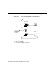
Connecting the Interface Cables and Checking the LEDs
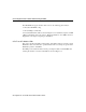
Table 8-2 LED Illumination States of CES T1 or CES E1 PAMs
Table 8-3 shows the possible status conditions of a CES T1or CES E1 port, as indicated by
certain settings of associated port LEDs.
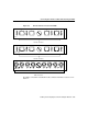
Table 8-3 Port Status Conditions Indicated by CES T1 or CES E1 LEDs
Note During alarm integration, the indicated LEDs will flash the “upcoming” or “next”
state combination indicated in Table 8-3. For example, when the line conditioning state
machine is notified of loss of signal (LOS), it will cause S1 and S2 to flash red, since a
continued LOS will put the port in the red alarm state.
Port LEDs Illumination States
S1 (status1) Steady green, red, or yellow; flashing green, red, or yellow; or off.
S2 (status2 Steady green, red, or yellow; flashing green, red, or yellow; or off.
CD (carrier detect) Either on (green) or off.
Port Status Indication S1 LED State S2 LED State CD LED State
Port not configured Off Off Off
Port administratively down Off Off Off
Normal Green Green Green
Red alarm due to framing error Red Red Off
Red alarm due to loss of cells Red Red Green
Yellow alarm Yellow Off Green
Blue alarm Off Yellow Green
Port in loop state Flashing green Flashing green Green