Cisco Virtual Wireless Controller Deployment Guide Document ID: 113677 Introduction Prerequisites Virtual Controller Support Virtual WLAN Controller Unsupported Features Single Virtual Controller Resource Requirement Suggested Hardware Recommendations for Hosting Cisco Virtual Controllers AP Requirement Components Used Topology Conventions Release Notes Virtual Controller Installation Virtual Controller Virtual Interfaces Switch Interface Configuration Connected to UCS Server VMware Promiscuous Mode Definit
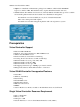
VMware benefits with the vWLC: • vSphere: A virtualization infrastructure package from VMware, which includes ESX/ESXi hypervisor, vMotion, DRS, HA, Fault Tolerance, vSphere Distributed Switch, and more.
Suggested Hardware Recommendations for Hosting Cisco Virtual Controllers • UCS R210−2121605W Rack Mount Server (2 RU): ♦ 2 * Intel Xeon CPU X5670 @ 2.93 GHz ♦ 16 G memory • IBM x3550 M3 Server: ♦ 2 * Intel Xeon 5600 series processors with 4 cores each and each core capable of doing hyper threading which gives you 16 CPUs in total @3.6 GHz ♦ 12G memory • ISR G2 Services Ready Engine (SRE) using UCS Express (Stretch goal): ♦ SRE 700: Single Core Intel Core Duo 1.
and local access to Internet). Conventions Refer to Cisco Technical Tips Conventions for more information on document conventions. Release Notes Cisco Unified Wireless Network (CUWN) 7.3 Release Notes contain important information about this release. Log in to Cisco.com for the latest release notes before loading and testing software.
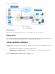
Virtual Controller Virtual Interfaces • Management Interface • Virtual Interface • Dynamic Interface • AP Manager Interface Switch Interface Configuration Connected to UCS Server This section provides a sample configuration of the Cisco Catalyst interface connection to the ESXi server for the virtual switch as trunk interface. The management interface can be connected to an access port on the switch.
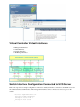
interface GigabitEthernet1/1/3 description ESXi Trunk switchport trunk encapsulation dot1q switchport mode trunk end Complete these steps: 1. Create two separate virtual switches in order to map to the virtual controller Service and Data Port. Go to ESX > Configuration > Networking, and click Add Networking. 2. Select Virtual Machine, and click Next. 3. Create a vSwitch and assign a physical NIC in order to connect the vWLC service port.
. Click Next. 8. Here, you see vSwitch1 is created for vWLC Service Port. Click Add Networking in order to repeat for the Data Port. 9. For the new vSwitch, select the physical NIC(s) connected on a trunk port if there are multiple NICs / portgroup assigned to an etherchannel on the switch. 10. Add the NIC. 11. Click Next. 12. Provide a label (in this example, vWLC Data Port). 13. For VLAN ID, select ALL(4095) since this is connected to a switch trunk port.
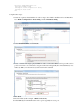
14. Click Next until you complete the steps to add the vSwitch. VMware Promiscuous Mode Definition Promiscuous mode is a security policy which can be defined at the virtual switch or portgroup level in vSphere ESX/ESXi. A virtual machine, Service Console, or VMkernel network interface in a portgroup which allows the use of promiscuous mode can see all network traffic traversing the virtual switch. By default, a guest operating system's virtual network adapter only receives frames that are meant for it.
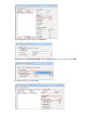
3. In the Properties window, select the Security tab. 4. Check the box for Promiscuous Mode, choose Accept from the drop−down list, and click OK. 5. Confirm the change, and click Close.
The virtual controller software is posted as an .ovf package in the Cisco software center. You can download the .ova/.ovf package and install to any other virtual application. The software comes with a free 60−day evaluation license. After the VM is started, the evaluation license can be activated and a purchased license can be automatically installed and activated later. 6. Download the virtual controller OVA image to the local disk. 7.
10. Provide a name for the vWLC or accept the default, and click Next. 11. Accept the default Thick Provision Lazy Zeroed setting, and click Next. 12. Accept the Network Mapping default, and click Next.
13. Confirm the Deployment settings, and click Finish in order to begin installation. 14. Click Close when Deployment is complete. Two important things to note regarding upgrading virtual controllers: • The OVA image is needed only for first time installation. • The .AES image can be subsequently used for upgrading/downgrading. Virtual Controller Settings After creating the virtual controller, configure the virtual machine settings to map networking and add a virtual serial console.
2. Select Network adapter 1 to vWLC Service Port (vSwitch created in ESX networking). 3. Map Network adapter 2 to vWLC Data Port. 4. Confirm the correct mapping. Virtual Controller Console Port The console port gives access to the console prompt of the WLC. As a result, the VM can be provisioned with serial ports in order to connect to these. In the absence of serial ports, the vSphere Client Console is connected to the console on the vWLC.
• Physical Serial Port on the Host: The vWLCs virtual serial port is mapped to the hardware serial port on the server. This option is limited to the number of physical serial port(s) on the host. If in a multi−tenant vWLC scenario, this may not be ideal. • Connect via Network: The vWLCs virtual serial port can be accessed using Telnet session from a remote machine to a specific port allocated for the VM on hypervisor. For example, if the hypervisors IP address is 10.10.10.
5. Click Next in order to review the Options, and click Finish. 6. Click OK in order to complete the configured settings. In order to enable for the serial via network, ESX must be configured to allow for such requests. 7. Navigate to the ESX, click the Configuration tab, go to Software > Security Profile, and click on Properties.
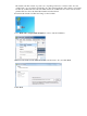
8. In the Firewall Properties window, select VM serial port connected to vSPC, and click OK. Start up the vWLC Complete these steps: 1. Start the vWLC, and select the console in order to observe the first−time installation process.
2. Monitor the progress until the VM console shows that the vWLC has restarted (this is automatic). 3. Open a Telnet session to the vWLC as shown here: 4. The Telnet session will now manage the console to the vWLC.
Note: Only one mode of console can be operational at any time, such as a VM console (by key−interrupt at startup) or serial console (physical/network). It is not possible to maintain both at the same time. 5. Continue to wait until the vWLC has come online fully and prompts you to start the configuration tool wizard. 6. Configure the management interface address / mask / gateway. Configure Management Interface VLAN ID if tagged. Continue with the remainder. 7.
configuration, which may result in APs not joining in the process. 8. Complete the configuration and allow the vWLC to reset. 9. It is suggested that you ping the vWLC management interface in order to ensure that it has come online. Log in to the vWLC. 10. You can issue the show interface summary command and ping the gateway from the vWLC. 11.
12. Initially, there are 0 (zero) Access Points Supported. Enable the evaluation license in order to allow the AP to join. 13. Go to Management > Software Activation > Licenses. Select base−ap−count, and set the Priority to High.
14. Click OK, and Accept the EULA in order to continue. 15. Click OK, and reset the vWLC in order for the evaluation license to take effect. 16. Reboot the vWLC.
17. Log back in to the vWLC, and note that the 200 APs are now supported with the evaluation license enabled. 18. Connect an AP, and monitor for the join message to occur. 19. From the browser, go to WIRELESS and confirm that the AP has joined. 20. Click the AP, and change the AP Mode to FlexConnect. Only FlexConnect is supported (central and local switching) in the 7.3 release.
21. It may be useful to consider using the autoconvert function of the controller (for example, any mode AP joining the vWLC will be converted automatically to FlexConnect). Issue this command in order to implement: (Cisco Controller) > config ap autoconvert flexconnect enable Virtual Controller Management with Cisco Prime 1.2 Cisco Prime Infrastructure version 1.2 is the minimum release required to centrally manage one or more Cisco Virtual Controller(s).
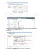
3. In Device Work Center, click Add Device. 4. Enter the IP Address and SNMP Community string (Read/Write). By default, the SNMP RW for the controller is Private. Click Add.
5. Cisco Prime Infrastructure will discover and synchronize with the virtual controller. Click refresh in order to update the screen. 6. When the virtual controller is discovered, it is listed as Managed and Reachable (shown in green). Add any other virtual controller(s) at this point, if available. 7. The new controller will be listed in Device Type > Cisco VIRTUAL Series Wireless LAN Controller.
8. Navigate to Home for a Summary view (in Lifecycle Theme) of the devices being managed. 9. For the remainder of this guide, the Classic Theme is used to perform similar task of adding the virtual controller, as well as updating the system image. Go to and select Switch to Classic Theme. 10. Go to Configure > Controllers. 11. In order to add a new virtual controller, select Add Controllers... from the Select a command drop−down list.
12. Enter the IP Address, Read/Write SNMP Community string, and click Add. 13. Cisco Prime Infrastructure will display this notification: 14. Go to Configure > Controllers. The virtual controller will be listed as Reachable once it has been successfully discovered and added. Otherwise, and as shown above, the device will appear in the Unknown Device page if it was not discovered successfully.
Upgrade the Virtual Controller In the early steps of installation, the Cisco Virtual Controller initially required an OVA file for new virtual appliance creation. However, maintaining virtual controller features and software upgrades require a common AES file downloadable from the Cisco website. Complete these steps: 1. Download the AS*7_3*aes file to a target host (for example, the TFTP/FTP server). 2. Just as for legacy controllers, go to the web GUI of the controller > COMMANDS > Download File.
4. Click Save and Reboot. 5. Cisco Prime Infrastructure can also be useful for upgrading one virtual controller or many virtual controllers at the same time. Go to Configure > Controllers. Select (check box) one or more virtual controllers. Select Download Software (TFTP) from the command drop−down list. This example uses TFTP mode for image upgrade. 6. Provide the Download Type, TFTP server (new if using external), IP Address, File Path, and Server File Name (which is the .aes file type). Click Download.
7. This screen is an example of the AES image being transferred to the virtual controllers: 8. Cisco Prime Infrastructure will update the status until the software has transferred successfully. 9. Similar to the experience directly from the controller, a reboot is required when the transfer is complete. In Cisco Prime Infrastructure, go to Configure > Controllers, and select the virtual controller(s). Select Reboot Controllers from the Select a command... drop−down list.
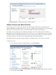
10. Cisco Prime Infrastructure will prompt for reboot parameters such as save configuration, and so forth. Click OK. 11. Cisco Prime Infrastructure will notify the administrator that the virtual controllers are being rebooted. 12. When complete, Cisco Prime Infrastructure will provide the results of the process. Troubleshooting AP Considerations Known Issue: AP(s) not joining vWLC − The AP must get the hash entry from a legacy controller before it joins a vWLC. • An AP must be at software version 7.3.1.
• The hash validation, which is an extra authorization step, will be performed only if the AP is joining a virtual controller. There will be a knob to turn on/off hash key validation. • By default, hash validation is enabled, which means that the AP needs to have the virtual controller hash key in its flash before it can successfully complete association with the virtual controller. If the knob is turned off, the AP will bypass the hash validation and move directly to the RUN state.
• The AP may have an older SSC hash, either from an old installation or joining other controllers. It is possible to configure the WLC to not validate SSC, allow APs to join the vWLC, then re−enabling the validation again. (Cisco Controller) >configure certificate ssc hash validation disable • Perform the test capwap command in order to clear AP capwap settings and initiate join process. APf866.f267.67af#test capwap erase APf866.f267.67af#test capwap restart restart capwap APf866.f267.