
- Cisco Network Router User's Manual


6-16
Cisco Intrusion Prevention System Appliance and Module Installation Guide for IPS 7.1
OL-24002-01
Chapter 6 Installing the IPS 4345 and IPS 4360
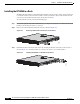
Removing and Installing the Power Supply
The power supplies each provide 400 W of output power and are used in a 1 + 1 redundant configuration.
There is no input switch on the faceplate of the power supplies. The power supply is switched from
Standby to ON by way of a system chassis STANDBY/ON switch. The power supply slot numbers are
on the back of the chassis to the left side of each power supply. When facing the back of the chassis,
power supply slot 0 (PS0) is to the left and power supply slot 1(PS1) is to the right. By default, the
factory installs a single power supply in slot 0.
The appliance supports the following power supplies:
•
AC power supply—Provides 400 watt output power with two DC voltage outputs: +12 V and +5 V.
The AC power supply operates between 85 and 264 VAC. The AC power supply current shares on
the 12 V output and is used in a dual hot pluggable configuration. The AC power supply consumes
a maximum of 471 W of input power.
•
DC power supply—Provides 400 watt output power with two DC voltage outputs: +12 V and +5.0
V. The power supply operates between –40.5 and –72 VDC. The DC power supply current shares on
the 12 V output and is used in a dual hot pluggable configuration. The DC power supply consumes
a maximum of 500 W of input power.
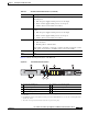
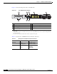
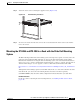
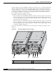
Figure 6-11 shows both the removable AC (on the left) and DC (on the right) power supplies for the
IPS 4360.
Figure 6-11 AC Power Supply and DC Power Supply
1 Power supply indicator 2 DC power supply positive connection
3 DC power supply neutral connection 4 DC power supply negative connection
11 2 3 4
333056