
User Manual
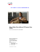
Table Of Contents
- Contents
- Preface
- Introduction
- Basic Set Up
- Viewing Live Video
- Advanced Viewing Set Up
- Managing an IP Camera through the Web
- Connecting to an IP Camera
- Basic Setup Window
- Advanced Setup Window
- IP Filter Window
- Users Window
- Maintenance Window
- Firmware Window
- Video Window
- Audio Window
- Mail Window
- Motion Detection Window
- Event Window
- SNMP Window
- DDNS Window
- I/O Ports Window
- RS-485 Window
- System Window
- Image Window
- Network Window
- Syslog & Log Window
- View Video Log Window
- Troubleshooting
- Streaming Video/Audio Solution
- Index

EFT DRAFT—CISCO CONFIDENTIAL
1-4
Cisco Video Surveillance IP Camera User Guide
OL-14220-01
Chapter 1 Introduction
Physical Details
Reset button This button is recessed. A pin or paper clip can be
used to depress it. It can be activated any time that
the camera is in the ready mode and can have these
affects:
• Restore Default IP Address—When this
button is pressed and released, the IP camera
resets to a static IP address of 192.168.0.100.
• Restore Default IP Address, Administrator ID,
and Administrator password—When this
button is pressed and held for 3 seconds, the IP
address, Administrator ID, and Administrator
Password settings are set to their default
values:
–
IP address: 192.168.0.100.
–
Administrator ID: admin
–
Administrator Password: admin
Note After a reset procedure completes, the
Ready LED blinks 3 times to confirm that
the reset was successful.
LAN port Use a standard LAN cable to connect the IP camera
to a 10/100BaseT hub or switch.
Note Attaching the LAN cable disables the
wireless interface. Only 1 interface can be
active at any time.
The LAN cable should be connected or
disconnected only when the camera is
powered off. Attaching or detaching the
LAN cable while the camera is powered
on does not switch the interface between
wired and wireless.
Network LED (amber) On—Wireless or LAN connection is detected.
Off—Wireless or LAN connection is not detected
Blinking—Data is being transmitted or received
via the LAN or wireless connection.
PoE LED (green) On—PoE connection is detected.
Off—PoE connection is not detected
Power Input Connect an optional 12 V, 1 amp DC power adapter
here.
Note The camera can also operate using PoE.
GPIO The GPIP terminal block includes 1 RS-485 port (2
pins), 2 input ports and 2 output ports.
Table 1-1 IP Camera Physical Details
Item Description