
- Cisco 1800 Series Integrated Services Router Manual

6-4
Cisco 1800 Series Routers (Modular) Hardware Installation Guide
OL-5876-03
Chapter 6 Cable Connection Procedures for Cisco 1800 Series Routers (Modular)
Connecting to a Console Terminal or Modem
Connecting to the Console Port
To configure the router through the Cisco IOS CLI, you must connect the router console port to a
terminal or PC. The cable required for this connection is included with the router.
The PC must have HyperTerminal or similar terminal emulation software installed. The software should
be configured with the following parameters: 9600
baud, 8 data bits, no parity, 1 stop bit, and no mode
control. See Cisco
1800 series router software configuration documents on Cisco.com for detailed
information about using Cisco
IOS software for configuring the router.
To connect the router to a terminal or PC, follow these steps:
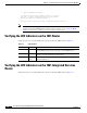
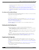
Step 1 Connect the end of the light blue console cable with the RJ-45 connector to the light blue console port
on the router, as shown in
Figure 6-1.
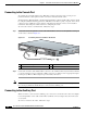
Figure 6-1 Connecting the Console Cable to the Router
Step 2 Connect the end of the cable with the DB-9 connector to the terminal or PC. If your terminal or PC has
a console port that does not accommodate a DB-9 connector, you must provide an appropriate adapter
for that port. (A DB-9-to-DB-25 adapter is provided with your router.)
Note Because mode control is not possible on the console port, we do not recommend connecting modems to
the console port. Modems should always be connected to the auxiliary port.
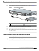
Connecting to the Auxiliary Port
When a modem is connected to the auxiliary port, a remote user can dial in to the router and configure
it. Use the light blue console cable and the DB-9-to-DB-25 connector adapter that came in the router
accessory kit.
To connect a modem to the router, follow these steps:
1 Light blue console port 3 To PC or terminal
2 Light blue console cable
122332
1
2
3
CISCO 1841
100-240 VAC-
1 A
50/60 Hz