
- Cisco 1800 Series Integrated Services Router Manual


4-11
Cisco 1800 Series Routers (Modular) Hardware Installation Guide
OL-5876-03
Chapter 4 Chassis Installation Procedures for Cisco 1800 Series Routers (Modular)
Installing the Chassis Ground Connection
Warning
To prevent bodily injury when mounting or servicing this unit in a rack, you must take special
precautions to ensure that the system remains stable. The following guidelines are provided to ensure
your safety:
-- This unit should be mounted at the bottom of the rack if it is the only unit in the rack.
-- When mounting this unit in a partially filled rack, load the rack from the bottom to the top with the
heaviest component at the bottom of the rack.
-- If the rack is provided with stabilizing devices, install the stabilizers before mounting or servicing
the unit in the rack.
Statement 1006
Caution Chassis installation must allow unrestricted airflow for chassis cooling.
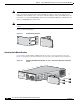
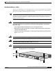
Tip The screw slots in the brackets are spaced to line up with every second pair of screw holes in the rack.
When the correct screw holes are used, the small threaded holes in the brackets line up with unused screw
holes in the rack. If the small holes do not line up with the rack holes, you must raise or lower the
brackets to the next rack hole.
Installing the Chassis Ground Connection
Warning
This equipment must be grounded. Never defeat the ground conductor or operate the equipment in the
absence of a suitably installed ground conductor. Contact the appropriate electrical inspection
authority or an electrician if you are uncertain that suitable grounding is available.
Statement 1024
Installing the Chassis Ground Connection on the Cisco 1841 Router
You must connect the chassis to a reliable earth ground, using a ground lug and size 14 AWG (2 mm
2
)
wire. To install the ground connection for a Cisco 1800 series router, follow these steps:
Step 1 Strip one end of the ground wire to expose approximately 0.75 in. (20 mm) of conductor.
Step 2 Crimp the 14 AWG green ground wire to a UL Listed/CSA certified ring terminal that is suitably sized
for the number 6 ground screw provided on the rear panel of the router. The crimping tool should be one
that is recommended by the ring lug terminal manufacturer.
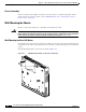
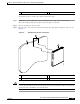
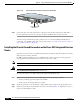
Step 3 Attach the ring terminal to the chassis. The attachment points for the Cisco 1841 router are shown in
Figure 4-11. Use a number 2 Phillips screwdriver and the screw supplied with the ground lug. Tighten
the screw to a torque of 8 to 10 in-lb. (0.9 to 1.1 N-m).