Cisco 1800 Series Integrated Services Routers (Modular) Hardware Installation Guide Americas Headquarters Cisco Systems, Inc. 170 West Tasman Drive San Jose, CA 95134-1706 USA http://www.cisco.
THE SPECIFICATIONS AND INFORMATION REGARDING THE PRODUCTS IN THIS MANUAL ARE SUBJECT TO CHANGE WITHOUT NOTICE. ALL STATEMENTS, INFORMATION, AND RECOMMENDATIONS IN THIS MANUAL ARE BELIEVED TO BE ACCURATE BUT ARE PRESENTED WITHOUT WARRANTY OF ANY KIND, EXPRESS OR IMPLIED. USERS MUST TAKE FULL RESPONSIBILITY FOR THEIR APPLICATION OF ANY PRODUCTS.
Contents CHAPTER 1 Introduction to Cisco 1800 Series Routers (Modular) Hardware Documentation Objectives Audience 1-5 1-6 Organization 1-6 Conventions 1-7 Safety Warnings 1-7 Related Documentation 1-13 Cisco One-Year Limited Hardware Warranty Terms Searching for Cisco Documents 1-14 1-15 Obtaining Documentation and Submitting a Service Request CHAPTER 2 Overview of Cisco 1800 Series Routers (Modular) 1-15 2-1 Hardware Features 2-2 Product Serial Number Location 2-3 Cisco Product Identi
Contents Site Configuration Installation Checklist Site Log 3-4 3-4 3-5 Inspecting the Router 3-6 Items in the Box for the Cisco 1841 Router 3-6 Items in the Box for the Cisco 1861 Integrated Services Router 3-6 Items not Included in the Box for the Cisco 1861 Integrated Services Router Required Tools and Equipment for Installation and Maintenance CHAPTER 4 3-7 3-7 Chassis Installation Procedures for Cisco 1800 Series Routers (Modular) Setting Up the Chassis 4-3 Setting the Chassis on a Desktop 4-3
Contents CHAPTER 6 Cable Connection Procedures for Cisco 1800 Series Routers (Modular) Power Connections 6-1 Connecting WAN and LAN Cables 6-2 Ports and Cabling 6-2 Connection Procedures and Precautions 6-3 Connecting to a Console Terminal or Modem 6-3 Connecting to the Console Port 6-4 Connecting to the Auxiliary Port 6-4 Connecting Power to the Cisco 1861 Integrated Services Router CHAPTER 7 Power-Up Procedures for Cisco 1800 Series Routers (Modular) Powering Up Cisco 1800 Series Routers Checkli
Contents CHAPTER Installing Interface Cards in Cisco 1800 Series Routers (Modular) 9 Cisco Interface Cards Installation Guide Related Product Documentation 9-1 9-1 9-1 Installing WICs, VWICs, and HWICs 9-1 CHAPTER 10 Installing and Replacing CompactFlash Memory Cards on Cisco 1800 Series Routers (Modular) 10-1 Preventing Electrostatic Discharge Damage 10-1 Replacing CompactFlash Memory Cards 10-1 Removing a CompactFlash Memory Card 10-2 Installing a CompactFlash Memory Card 10-2 Using the Compac
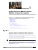
CH A P T E R 1 Introduction to Cisco 1800 Series Routers (Modular) Hardware Documentation This introduction discusses the objectives, audience, organization, and conventions of the hardware documents for the Cisco 1800 series integrated services routers (modular), and describes related documents that have additional information.
Chapter 1 Introduction to Cisco 1800 Series Routers (Modular) Hardware Documentation Audience Audience This documentation is designed for the person installing, configuring, and maintaining the router, who should be familiar with electronic circuitry and wiring practices and has experience as an electronic or electromechanical technician. The documentation identifies those procedures that should be performed only by trained and qualified personnel.
Chapter 1 Introduction to Cisco 1800 Series Routers (Modular) Hardware Documentation Conventions Conventions This documentation uses the conventions listed in Table 1-2 to convey instructions and information. Table 1-2 Document Conventions Convention Description boldface font Commands and keywords. italic font Variables for which you supply values. [ Optional keywords or arguments appear in square brackets.
Chapter 1 Introduction to Cisco 1800 Series Routers (Modular) Hardware Documentation Safety Warnings Note Warning The title Regulatory Compliance and Safety Information for Cisco 1840 Routers refers to a specific chassis model: the Cisco 1840. The Cisco 1841 router received compliance certification under the chassis model Cisco 1840. The same regulatory compliance and safety information for the Cisco 1841 router is applicable to the Cisco 1861 ISR.
Chapter 1 Introduction to Cisco 1800 Series Routers (Modular) Hardware Documentation Safety Warnings Warnung WICHTIGE SICHERHEITSHINWEISE Dieses Warnsymbol bedeutet Gefahr. Sie befinden sich in einer Situation, die zu Verletzungen führen kann. Machen Sie sich vor der Arbeit mit Geräten mit den Gefahren elektrischer Schaltungen und den üblichen Verfahren zur Vorbeugung vor Unfällen vertraut.
Chapter 1 Introduction to Cisco 1800 Series Routers (Modular) Hardware Documentation Safety Warnings Varning! VIKTIGA SÄKERHETSANVISNINGAR Denna varningssignal signalerar fara. Du befinner dig i en situation som kan leda till personskada. Innan du utför arbete på någon utrustning måste du vara medveten om farorna med elkretsar och känna till vanliga förfaranden för att förebygga olyckor.
Chapter 1 Introduction to Cisco 1800 Series Routers (Modular) Hardware Documentation Safety Warnings Aviso INSTRUÇÕES IMPORTANTES DE SEGURANÇA Este símbolo de aviso significa perigo. Você se encontra em uma situação em que há risco de lesões corporais. Antes de trabalhar com qualquer equipamento, esteja ciente dos riscos que envolvem os circuitos elétricos e familiarize-se com as práticas padrão de prevenção de acidentes.
Chapter 1 Introduction to Cisco 1800 Series Routers (Modular) Hardware Documentation Safety Warnings Cisco 1800 Series Routers (Modular) Hardware Installation Guide 1-12 OL-5876-03
Chapter 1 Introduction to Cisco 1800 Series Routers (Modular) Hardware Documentation Related Documentation Related Documentation The Cisco IOS software that runs your Cisco 1800 series router includes extensive features and functionality. For information that is beyond the scope of this document, or for additional information, see Table 1-3. Timesaver Make sure that you have access to the documents listed in Table 1-3. Some of these documents are available in print, and all are available on Cisco.com.
Chapter 1 Introduction to Cisco 1800 Series Routers (Modular) Hardware Documentation Cisco One-Year Limited Hardware Warranty Terms Table 1-3 Related and Referenced Documents Cisco Product Document Title Cisco 1800 series routers Cisco 1800 Series Integrated Services Routers (Modular) Quick Start Guide Cisco 1800 Series Software Configuration Cisco Network Modules and Interface Cards Regulatory Compliance and Safety Information Regulatory Compliance and Safety Information for Cisco 1840 Routers Cisc
Chapter 1 Introduction to Cisco 1800 Series Routers (Modular) Hardware Documentation Searching for Cisco Documents Replacement, Repair, or Refund Policy for Hardware Cisco or its service center will use commercially reasonable efforts to ship a replacement part within ten (10) working days after receipt of a Return Materials Authorization (RMA) request. Actual delivery times can vary, depending on the customer location.
Chapter 1 Introduction to Cisco 1800 Series Routers (Modular) Hardware Documentation Obtaining Documentation and Submitting a Service Request Cisco 1800 Series Routers (Modular) Hardware Installation Guide 1-16 OL-5876-03
CH A P T E R 2 Overview of Cisco 1800 Series Routers (Modular) Cisco 1800 series integrated services routers (ISR) (modular) are modular routers with LAN and WAN connections that can be configured by means of interchangeable interface cards and advanced integration modules (AIMs). The modular design of the routers provides flexibility, allowing you to configure or reconfigure your router according to your needs. The Cisco 1841 router is a data-only device for desktop use.
Chapter 2 Overview of Cisco 1800 Series Routers (Modular) Hardware Features Figure 2-2 The Cisco 1861 Integrated Services Router with FXO Ports SYS POE Cisco 18 00 1 231626 VM Series 2 3 1 WAN slot 2 FXO ports 3 Figure 2-3 Expansion switch port The Cisco 1861 Integrated Services Router with BRI Ports 1 SYS POE 1 Cisco 18 00 231625 VM Series 00 2 3 4 1 BRI ports 3 FXS ports 2 Power over Ethernet (PoE) ports 4 Fast Ethernet (FE) port This chapter describes the features and
Chapter 2 Overview of Cisco 1800 Series Routers (Modular) Hardware Features • Interfaces, page 2-3 • Removable and Interchangeable Modules, page 2-5 • Memory, page 2-5 • LED Indicators, page 2-6 • Chassis Ventilation, page 2-7 • Real-Time Clock, page 2-7 • Chassis Security, page 2-8 Product Serial Number Location The serial number label for the Cisco 1841 router and the Cisco 1861 ISR is located on the rear of the chassis, underneath interface card slot 0. (See Figure 2-4.
Chapter 2 Overview of Cisco 1800 Series Routers (Modular) Hardware Features Interfaces on the Cisco 1841 Router The following interfaces exist on the Cisco 1841 router: • Two Fast Ethernet ports (RJ-45 connectors) • High-speed console and auxiliary ports, up to 115.2 kbps each (RJ-45 connectors) • One USB port (version 1.
Chapter 2 Overview of Cisco 1800 Series Routers (Modular) Hardware Features Table 2-1 Cisco 1861 Integrated Services Router: Interfaces Description Label Value in Software Configuration (Factory Option) VIC: FXO* VIC2-2FXO and 0-1 port 0/2/0 to 0/2/1 VIC2-4FXO and 0-3 or port 0/2/0 to 0/2/3 (Factory Option) VIC: FXS* VIC3-2FXS/DID and 0-1 port 0/2/0 to 0/2/1 VIC-4FXS/DID and 0-3 or VIC3-4FXS/DID and 0-3 port 0/2/0 to 0/2/3 * Only one optional VIC can be factory installed in a Cisco 1861 I
Chapter 2 Overview of Cisco 1800 Series Routers (Modular) Hardware Features • Boot/NVRAM—Serves two functions. It stores the ROM monitor, which allows you to boot an operating system software image from flash memory. It also stores the system configuration file and the virtual configuration register. Table 2-3 lists the memory specifications for Cisco 1800 series routers.
Chapter 2 Overview of Cisco 1800 Series Routers (Modular) Hardware Features Table 2-5 Summary of Cisco 1800 Series LED Indicators (continued) LED Color Description Location: 100 (FE 0/1) Green On indicates a 100-Mbps link. Off indicates a 10-Mbps link. Back Link (FE 0/1) Green On when the router is correctly connected to a local Ethernet LAN through Ethernet port 1. Back AIM Green On indicates presence of an AIM in the internal AIM slot.
Chapter 2 Overview of Cisco 1800 Series Routers (Modular) Chassis Views Note If the lithium battery in a Cisco 1841 router should fail, the router must be returned to Cisco for repair. Do not replace the battery yourself. Although the battery is not intended to be field replaceable, the safety agencies require the following warning be included in this document. Warning There is the danger of explosion if the battery is replaced incorrectly.
Chapter 2 Overview of Cisco 1800 Series Routers (Modular) Interface Numbering 1 Input power connection 8 CompactFlash memory card slot 2 On/Off switch 9 CompactFlash (CF) LED 3 Slot 0 (WIC, VWIC—data only, or HWIC) 10 AIM LED 4 Console port 11 USB port 5 Fast Ethernet ports and LEDs 12 Aux port TM 6 Kensington 13 Chassis ground connection 7 Slot 1 (WIC, VWIC—data only, or HWIC) security slot Interface Numbering Each individual interface (port) on a Cisco 1841 router is identified by
Chapter 2 Overview of Cisco 1800 Series Routers (Modular) Interface Numbering on the 1861 Integrated Services Router Interface Numbering on the 1861 Integrated Services Router Each interface (port) on a Cisco 1861 ISR is identified by a number.
Chapter 2 Overview of Cisco 1800 Series Routers (Modular) Specifications Specifications Table 2-8 lists the specifications for Cisco 1800 series routers. Table 2-8 1841 Router Specifications Description Specification Dimensions without rubber feet (H x W x D) 1.73 x 13.5 x 10.8 in. (4.4 x 34.3 x 27.4 cm) With rubber feet, height is 1.87 in. (4.75 cm) Weight (no modules installed) 6.1 lb. (2.
Chapter 2 Overview of Cisco 1800 Series Routers (Modular) Regulatory Compliance Cisco 1800 Series Routers (Modular) Hardware Installation Guide 2-12 OL-5876-03
CH A P T E R 3 Preinstallation Requirements and Planning for Cisco 1800 Series Routers (Modular) This chapter describes the site requirements and equipment needed to install your Cisco 1800 series integrated services router (modular).
Chapter 3 Preinstallation Requirements and Planning for Cisco 1800 Series Routers (Modular) Safety Recommendations Warning Blank faceplates and cover panels serve three important functions: they prevent exposure to hazardous voltages and currents inside the chassis; they contain electromagnetic interference (EMI) that might disrupt other equipment; and they direct the flow of cooling air through the chassis.
Chapter 3 Preinstallation Requirements and Planning for Cisco 1800 Series Routers (Modular) General Site Requirements • Never open the enclosure of the router’s internal power supply. • If an electrical accident occurs, proceed as follows: – Use caution; do not become a victim yourself. – Turn off power to the device. – If possible, send another person to get medical aid. Otherwise, assess the victim’s condition and then call for help.
Chapter 3 Preinstallation Requirements and Planning for Cisco 1800 Series Routers (Modular) Installation Checklist Warning The device is designed for connection to TN and IT power systems. Statement 1007 The AC power supply includes the following features: • Autoselects either 110 V or 220 V operation. • All units include a 6-foot (1.8-meter) electrical power cord. (A label near the power cord indicates the correct voltage, frequency, current draw, and power dissipation for the unit.
Chapter 3 Preinstallation Requirements and Planning for Cisco 1800 Series Routers (Modular) Site Log Installation Checklist for Site_____________________________________________ Router Name_______________________________________________________ Task Verified by Date Installation Checklist copied Background information placed in Site Log Site power voltages verified Installation site power check completed Required tools available Additional equipment available Router received Router quick start guide re
Chapter 3 Preinstallation Requirements and Planning for Cisco 1800 Series Routers (Modular) Inspecting the Router – Intermittent problems – Comments and notes Inspecting the Router Do not unpack the router until you are ready to install it. If the final installation site will not be ready for some time, keep the chassis in its shipping container to prevent accidental damage. When you are ready to install the router, proceed with unpacking it.
Chapter 3 Preinstallation Requirements and Planning for Cisco 1800 Series Routers (Modular) Required Tools and Equipment for Installation and Maintenance – Assembly hardware (screws) – Installing Components for Cisco 1861 Integrated Services Router Inspect all items for shipping damage. If anything appears to be damaged, or if you encounter problems installing or configuring your router, contact customer service.
Chapter 3 Required Tools and Equipment for Installation and Maintenance Preinstallation Requirements and Planning for Cisco 1800 Series Routers (Modular) Cisco 1800 Series Routers (Modular) Hardware Installation Guide 3-8 OL-5876-03
CH A P T E R 4 Chassis Installation Procedures for Cisco 1800 Series Routers (Modular) This chapter tells how to physically set up Cisco 1800 series integrated services routers (ISR) (modular). It contains the following sections: • Setting Up the Chassis, page 4-3 • Installing the Chassis Ground Connection, page 4-11 Cisco 1800 series routers are normally shipped with a complement of components that can be upgraded or replaced to expand and enhance the router’s functionality.
Chapter 4 Chassis Installation Procedures for Cisco 1800 Series Routers (Modular) Interfaces on the Cisco 1861 Integrated Services Router The Cisco 1861 Integrated Services Router comes with various possible configurations, based on built-in ports and other hardware features of the Cisco 1861 Integrated Services Router and organized by model.
Chapter 4 Chassis Installation Procedures for Cisco 1800 Series Routers (Modular) Setting Up the Chassis Setting Up the Chassis The Cisco 1841 router and the Cisco 1861 ISR can be installed on a desktop, and can also be mounted on a wall. Select the setup that best meets the needs of your network.
Chapter 4 Chassis Installation Procedures for Cisco 1800 Series Routers (Modular) Setting Up the Chassis Note To install a Cisco 1800 series modular-configuration router in a 19-inch rack, use the brackets included in the optional rack-mount kit (SKU: ACS-1841-RM-19=).All Cisco 1841 chassis shipping since Q4FY06 are rack-mountable.
Chapter 4 Chassis Installation Procedures for Cisco 1800 Series Routers (Modular) Setting Up the Chassis Installing the Router in a Rack After you attach the brackets to the router chassis, use the screws provided with the rack to install the chassis in the rack. (See Figure 4-3.) Start with the lower pair of screws first, and rest the brackets on the lower screws while you insert the upper pair of screws.
Chapter 4 Chassis Installation Procedures for Cisco 1800 Series Routers (Modular) Setting Up the Chassis Chassis Grounding After the router has been installed, you must connect the chassis to a reliable earth ground. For the chassis ground connection procedure, see the “Wall-Mounting the Cisco 1861 Integrated Services Router” section on page 4-8. Wall-Mounting the Chassis The Cisco 1841 router and the Cisco 1861 ISR can be mounted on a wall. Warning This unit is intended to be mounted on a wall.
Chapter 4 Chassis Installation Procedures for Cisco 1800 Series Routers (Modular) Setting Up the Chassis 1 Wall-mounting features To mount the router on a wall or other surface, follow these steps: Step 1 Install the two screws 6.00 in. (15.2 cm) horizontally apart on a wall or other vertical surface. The screws should protrude 0.25 in. (0.6 cm) from the surface of the wall. Step 2 Remove the rubber feet from the router. Step 3 Hang the router on the screws, front panel down.
Chapter 4 Chassis Installation Procedures for Cisco 1800 Series Routers (Modular) Setting Up the Chassis Wall-Mounting the Cisco 1861 Integrated Services Router The Cisco 1861 Integrated Services Router has two keyholes on the bottom of the chassis for mounting the unit on a wall or other vertical surface. The power supply is mounted to the wall by using the wall-mount bracket. Figure 4-6 shows the bottom of the Cisco 1861 Integrated Services Router and the locations of the wall-mount holes.
Chapter 4 Chassis Installation Procedures for Cisco 1800 Series Routers (Modular) Setting Up the Chassis Step 3 Align the mounting-screw holes with a wall stud, or use wall anchors. a. For attaching to a wall stud, use two #10 wood screws (round- or pan-head) with #10 washers, or two #10 washer-head screws. The screws must be long enough to penetrate at least 3/4 inch (20 mm) into supporting wood or into a metal wall stud. b. For hollow-wall mounting, the wall must be at least 1/2 in. (12.7 mm) thick.
Chapter 4 Chassis Installation Procedures for Cisco 1800 Series Routers (Modular) Setting Up the Chassis Figure 4-9 shows the brackets in the rack-mount kit for the power supply. Figure 4-9 Brackets for Rack-Mounting Power Supply 242659 2 1 1 Step 2 Step 3 Wall-mount bracket 2 Rack-mount bracket Position the power supply in the wall-mount bracket. a. Orient the front and back of the power supply vertically. b. Position the end nearest the power cable at the top.
Chapter 4 Chassis Installation Procedures for Cisco 1800 Series Routers (Modular) Installing the Chassis Ground Connection Warning Caution Tip To prevent bodily injury when mounting or servicing this unit in a rack, you must take special precautions to ensure that the system remains stable. The following guidelines are provided to ensure your safety: -- This unit should be mounted at the bottom of the rack if it is the only unit in the rack.
Chapter 4 Chassis Installation Procedures for Cisco 1800 Series Routers (Modular) Installing the Chassis Ground Connection Chassis Ground Connection on the Cisco 1841 Router CISCO 1841 100-240 VAC1A 50/60 Hz 117083 Figure 4-11 Ring terminal attachment Step 4 Connect the other end of the ground wire to a known good electrical ground point. Consult with a licensed electrician if you have any questions about the suitability of the ground connection.
Chapter 4 Chassis Installation Procedures for Cisco 1800 Series Routers (Modular) Installing the Chassis Ground Connection Attaching the Ground Wire to the Chassis 230868 Figure 4-12 Step 4 Connect the other end of the ground wire to a known reliable earth ground point. Note If there is any doubt as to the reliability of the ground point, contact a licensed electrician for assistance.
Chapter 4 Chassis Installation Procedures for Cisco 1800 Series Routers (Modular) Installing the Chassis Ground Connection Cisco 1800 Series Routers (Modular) Hardware Installation Guide 4-14 OL-5876-03
CH A P T E R 5 Cable Information and Specifications for Cisco 1800 Series Routers (Modular) This chapter gives cable information and specifications for the console port, auxiliary port, and network ports on your Cisco 1800 series integrated services router (modular).
Chapter 5 Cable Information and Specifications for Cisco 1800 Series Routers (Modular) Preparing to Connect to a Network The default parameters for the console port are 9600 baud, 8 data bits, no parity, and 1 stop bit. The console port does not support mode control. For cable and port pinouts, see Cisco Modular Access Router Cable Specifications. Auxiliary Port Connections The router has an EIA/TIA-232 asynchronous serial auxiliary port (RJ-45) that supports flow control.
Chapter 5 Cable Information and Specifications for Cisco 1800 Series Routers (Modular) Preparing to Connect to a Network See Cisco Modular Access Router Cable Specifications for information about Ethernet cables, connectors, and pinouts. Serial Connections Serial connections are provided by serial WAN interface cards (WICs). For more information on WICs, see Installing Cisco Interface Cards in Cisco Access Routers.
Chapter 5 Cable Information and Specifications for Cisco 1800 Series Routers (Modular) Preparing to Connect to a Network The synchronous serial port can be configured as DTE or DCE, depending on the attached cable (except EIA-530, which is DTE only). To order a shielded cable, contact customer service. See the “Obtaining Documentation and Submitting a Service Request” section on page 1-15.
Chapter 5 Cable Information and Specifications for Cisco 1800 Series Routers (Modular) Preparing to Connect to a Network ISDN BRI Connections The BRI WICs provide ISDN and BRI connections. BRI WICs are available with either an S/T interface that requires an external Network Termination 1 (NT1), or a U interface that has a built-in NT1. You can install the BRI WICs in any available WIC slots in the chassis.
Chapter 5 Cable Information and Specifications for Cisco 1800 Series Routers (Modular) Preparing to Connect to a Network Cisco 1800 Series Routers (Modular) Hardware Installation Guide 5-6 OL-5876-03
CH A P T E R 6 Cable Connection Procedures for Cisco 1800 Series Routers (Modular) This chapter describes how to connect your Cisco 1800 series integrated services router (modular) to a power source and to networks and external devices.
Chapter 6 Cable Connection Procedures for Cisco 1800 Series Routers (Modular) Connecting WAN and LAN Cables Connecting WAN and LAN Cables This section describes how to connect the WAN and LAN interface cables. It includes the following: Note Warning • Ports and Cabling, page 6-2 • Connection Procedures and Precautions, page 6-3 One or two Ethernet cables are typically provided with the router. You can order additional network connection cables and transceivers from Cisco.
Chapter 6 Cable Connection Procedures for Cisco 1800 Series Routers (Modular) Connecting to a Console Terminal or Modem Table 6-1 WAN and LAN Connections (continued) Port or Connection Port Type, Color1 Connected to: DSL RJ-11C/RJ-14C Network demarcation RJ-11 straight-through for device for service provider’s 2-wire DSL interface RJ-14 straight-through for 4-wire BRI S/T WAN (external NT12) RJ-45, orange NT1 device or PINX3 RJ-45 straight-through BRI U WAN (built-in NT1) RJ-49C/CA-A11, orang
Chapter 6 Cable Connection Procedures for Cisco 1800 Series Routers (Modular) Connecting to a Console Terminal or Modem Connecting to the Console Port To configure the router through the Cisco IOS CLI, you must connect the router console port to a terminal or PC. The cable required for this connection is included with the router. The PC must have HyperTerminal or similar terminal emulation software installed.
Chapter 6 Cable Connection Procedures for Cisco 1800 Series Routers (Modular) Connecting to a Console Terminal or Modem Step 1 Connect the RJ-45 end of the adapter cable to the black AUX port on the router. (See Figure 6-2.) Figure 6-2 Connecting a Modem to the Router CISCO 1841 2 122333 100-240 VAC1A 50/60 Hz 1 3 4 1 Aux port (RJ-45) 3 DB-9-to-DB-25 modem adapter 2 Light blue console cable 4 Modem Step 2 Connect the DB-9 end of the console cable to the DB-9 end of the modem adapter.
Chapter 6 Cable Connection Procedures for Cisco 1800 Series Routers (Modular) Connecting to a Console Terminal or Modem Cisco 1800 Series Routers (Modular) Hardware Installation Guide 6-6 OL-5876-03
CH A P T E R 7 Power-Up Procedures for Cisco 1800 Series Routers (Modular) This chapter describes how to power up Cisco 1800 series integrated services routers (modular) and perform an initial configuration to provide network access.
Chapter 7 Power-Up Procedures for Cisco 1800 Series Routers (Modular) Powering Up Cisco 1800 Series Routers This section covers the following topics: • Checklist for Power Up, page 7-2 • LED Indicators, page 7-2 • Power-Up Procedure, page 7-2 Checklist for Power Up You may power up the Cisco router if the following steps have been completed: Note • Mount and ground the chassis securely. • Connect the power and interface cables.
Chapter 7 Power-Up Procedures for Cisco 1800 Series Routers (Modular) Powering Up Cisco 1800 Series Routers If you encounter problems when you power up the router, see Chapter 8, “Troubleshooting Cisco 1800 Series Routers (Modular).” For information about the ROM monitor and the bootstrap program, see the “Using the ROM Monitor” section of the Cisco 1800 Series Router Software Configuration.
Chapter 7 Power-Up Procedures for Cisco 1800 Series Routers (Modular) Verifying the LED Indicators on the 1841 Router . --- System Configuration Dialog --At any point you may enter a question mark '?' for help. Use ctrl-c to abort configuration dialog at any prompt. Default settings are in square brackets '[]'. Would you like to enter the initial configuration dialog? [yes/no]: Note If the rommon 1> prompt appears, your system has booted in ROM monitor mode.
Chapter 7 Power-Up Procedures for Cisco 1800 Series Routers (Modular) Verifying the Hardware Configuration Figure 7-1 LEDs on the Front Panel of the Cisco 1861 Integrated Services Router SYS 1 POE VM 230870 WLAN 4 3 2 1 1 SYS Solid green Online 2 POE Solid green Connected 3 VM Solid green Online 4 WLAN Blinking green Connected Verifying the Hardware Configuration Verify the router hardware configuration by using the following commands: • show version—Displays the system hardware v
Chapter 7 Power-Up Procedures for Cisco 1800 Series Routers (Modular) Initial Configuration of the Router • Cisco Router and Security Device Manager—See the “Cisco Router and Security Device Manager” section on page 7-6 • Setup command facility—See the “Initial Configuration Using the Setup Command Facility” section in the Cisco 1800 Series Integrated Services Routers (Modular) Quick Start Guide.
Chapter 7 Power-Up Procedures for Cisco 1800 Series Routers (Modular) Powering up the Cisco 1861 Integrated Services Router • Feature documentation • Troubleshooting and maintenance • Cisco 1800 series cards and modules Powering up the Cisco 1861 Integrated Services Router To power up the Cisco 1861 Integrated Services Router, perform the following steps: Step 1 Verify that the AC power cord is connected to the power supply.
Chapter 7 Power-Up Procedures for Cisco 1800 Series Routers (Modular) Software Components of the Cisco 1861 Integrated Services Router Table 7-2 Cisco 1861 Integrated Services Router Software Components (continued) Software Component Description Benefits Security Protects against Integrated for a robust array of security features. information theft, virus outbreaks, and application abuse, whether from known or unknown threats, internal or external sources.
CH A P T E R 8 Troubleshooting Cisco 1800 Series Routers (Modular) If you encounter problems with your Cisco 1800 series integrated services router (ISR) (modular), the information in this chapter can help you isolate problems in the router or eliminate the router as the source of the problem.
Chapter 8 Troubleshooting Cisco 1800 Series Routers (Modular) Problem Solving When solving problems, consider the following router subsystems: • Power and cooling systems—External power source, power cable, router power supply, circuit breaker, and router fan. Also check for inadequate ventilation or air circulation. • Interface cards—LEDs on the interface cards help identify a failure. • Cables—External cables that connect the router to the network.
Chapter 8 Troubleshooting Cisco 1800 Series Routers (Modular) Problem Solving Environmental Reporting Features If the router is operating at an abnormally high temperature, consider the following causes: • Fan failure • Air conditioner failure in the room • Air blockage to cooling vents Take steps to correct the problem. See the “Site Environment” section on page 3-4.
Chapter 8 Troubleshooting Cisco 1800 Series Routers (Modular) Reading LEDs – There may be a problem with the card or cable. See the “Cisco One-Year Limited Hardware Warranty Terms” and the “Obtaining Documentation and Submitting a Service Request” sections of the “Introduction to Cisco 1800 Series Routers (Modular) Hardware Documentation” document for warranty and customer service contact information. Reading LEDs The LEDs on the router enable you to determine router performance and operation.
Chapter 8 Troubleshooting Cisco 1800 Series Routers (Modular) System Messages Table 8-1 LED Indicator LED Indicators on Cisco 1800 Series Routers (continued) State CF Off (CompactFlash Busy) Blinking green Meaning Possible Causes and Corrective Actions The CompactFlash memory card is not being accessed. Normal indication. No action is required. It is okay to remove the CompactFlash memory card if the CF LED remains off. The CompactFlash memory card is being accessed. Normal indication.
Chapter 8 Troubleshooting Cisco 1800 Series Routers (Modular) Recovering a Lost Password The terminal should display one of the following prompts: Router> (indicates the user EXEC command mode) or Router# (indicates the privileged EXEC command mode) The Cisco IOS software checks the system condition once every 30 seconds. If a condition still exists, the error message is displayed again; if the error condition has cleared, a recovery message is displayed.
CH A P T E R 9 Installing Interface Cards in Cisco 1800 Series Routers (Modular) Cisco Interface Cards Installation Guide The Cisco Interface Cards Installation Guide contains the procedures for installing the various types of interface cards in external chassis slots.
Chapter 9 Installing Interface Cards in Cisco 1800 Series Routers (Modular) Installing WICs, VWICs, and HWICs To install a card in a Cisco 1841 router, follow these steps: Step 1 Make sure that the router is turned off and is disconnected from power. Caution Power must be removed from the system prior to installing or removing interface cards to avoid damaging them.
Chapter 9 Installing Interface Cards in Cisco 1800 Series Routers (Modular) Installing WICs, VWICs, and HWICs Step 5 Insert the card in the slot, and gently push it into the router until the front panel of the card is flush with the back panel of the router. Step 6 Tighten the screws.
Chapter 9 Installing Interface Cards in Cisco 1800 Series Routers (Modular) Installing WICs, VWICs, and HWICs Cisco 1800 Series Routers (Modular) Hardware Installation Guide 9-4 OL-5876-03
CH A P T E R 10 Installing and Replacing CompactFlash Memory Cards on Cisco 1800 Series Routers (Modular) This chapter describes installing and replacing CompactFlash memory cards in Cisco 1800 series integrated services routers (ISR) (modular). You can perform these procedures when the router has been installed in its working location with all power and interface cables connected.
Chapter 10 Installing and Replacing CompactFlash Memory Cards on Cisco 1800 Series Routers (Modular) Removing a CompactFlash Memory Card To remove a CompactFlash memory card from an external slot, follow these steps: Caution If the CF LED is on or blinking, do not remove the CompactFlash memory card. The router could crash, or the flash memory contents could be corrupted. Step 1 Press the ejector button next to the CompactFlash memory card.
Chapter 10 Installing and Replacing CompactFlash Memory Cards on Cisco 1800 Series Routers (Modular) Note A small flat-head screwdriver is required to attach the CF-guard. To install the CF-guard, follow these steps: Unpack the CF-guard. Step 2 Slip the CF-guard flap into the notch in the CompactFlash memory slot. Step 3 Screw the CF-guard into the screw hole.
Chapter 10 Installing and Replacing CompactFlash Memory Cards on Cisco 1800 Series Routers (Modular) Cisco 1800 Series Routers (Modular) Hardware Installation Guide 10-4 OL-5876-03
CH A P T E R 11 Installing and Upgrading Internal Modules in Cisco 1800 Series Routers (Modular) This chapter describes how to install or upgrade modules that are located internally within the Cisco 1800 series integrated services routers (modular): memory modules and advanced integration modules (AIMs). You need to remove the cover from the router to install or remove any of these items.
Chapter 11 Installing and Upgrading Internal Modules in Cisco 1800 Series Routers (Modular) Modules Internal to the Cisco 1841 Router Warning Hazardous network voltages are present in WAN ports regardless of whether power to the router is OFF or ON. To avoid electric shock, use caution when working near WAN ports. When detaching cables, detach the end away from the router first.
Chapter 11 Installing and Upgrading Internal Modules in Cisco 1800 Series Routers (Modular) Modules Internal to the Cisco 1841 Router Figure 11-1 Removing the Chassis Screw 103164 1 1 Step 4 Router cover fastening screw Insert a flat-head screwdriver into the slots at the screwdriver pry points and rotate the screwdriver 90 degrees to disengage the top cover from the chassis. See Figure 11-2.
Chapter 11 Installing and Upgrading Internal Modules in Cisco 1800 Series Routers (Modular) Modules Internal to the Cisco 1841 Router Figure 11-3 Removing the Cover of the Cisco 1841 Router 1 1 Step 7 Slide cover back from router chassis 2 103165 2 Rotate cover to remove from router chassis Place the router bottom on an antistatic mat, and begin installing memory. Locating Modules Figure 11-4 shows where the connector for the SODIMM or the AIM is located on the Cisco 1841 motherboard.
Chapter 11 Installing and Upgrading Internal Modules in Cisco 1800 Series Routers (Modular) Modules Internal to the Cisco 1841 Router Figure 11-4 Cisco 1841 Interior 10 6 9 11 8 7 1 95906 2 6 3 5 1 Caution 4 1 Ground screw 7 AIM module 2 Interface card slot 0 8 SODIMM socket 3 USB port 9 Power supply connection 4 CompactFlash memory card slot 10 System fan 5 Interface card slot 1 11 Power supply 6 Safety shields for WIC/HWIC slots and connectors Do not, under any circumstan
Chapter 11 Installing and Upgrading Internal Modules in Cisco 1800 Series Routers (Modular) Modules Internal to the Cisco 1841 Router Figure 11-5 Removing a SODIMM 3 1 103155 2 Step 3 1 Spring-loaded clips 2 SODIMM 3 SODIMM socket Insert the SODIMM into the SODIMM socket, as shown in Figure 11-6. Figure 11-6 Installing a SODIMM 1 2 103154 3 Step 4 1 SODIMM 2 Insert and rotate into socket.
Chapter 11 Installing and Upgrading Internal Modules in Cisco 1800 Series Routers (Modular) Modules Internal to the Cisco 1841 Router Table 11-1 AIMs Supported on Cisco 1841 Router Cisco Part Number Type AIM-CUE= Unity Express AIM2-CUE-K9 Unity Express AIM2-APPRE-104-K9 AXP—Application eXtension Platform AIM-IPS Intrusion Prevention Systems AIM-VPN-EPII-PLUS VPN Encryption Caution When you install an AIM, always wear an ESD-preventive wrist strap, and ensure that it makes good contact with
Chapter 11 Installing and Upgrading Internal Modules in Cisco 1800 Series Routers (Modular) Modules Internal to the Cisco 1841 Router Figure 11-7 Location of Metal Standoff Attachment Locations 121107 System board AIM connector Step 2 Caution Step 3 Install the two metal standoffs from the accessory kit into the system board in the metal standoff attachment locations, as shown in Figure 11-9. Use a 1/4-inch nut driver to tighten the standoffs.
Chapter 11 Installing and Upgrading Internal Modules in Cisco 1800 Series Routers (Modular) Modules Internal to the Cisco 1841 Router Figure 11-8 Plastic Standoff Orientation Locking end Step 4 Insert the connector on the AIM into the AIM connector on the system board. See Figure 11-9. Note Step 5 82620 AIM end Be sure to press firmly on the AIM until the board seats onto the connector. The plastic standoff must snap into the hole in the AIM board. See Figure 11-9.
Chapter 11 Installing and Upgrading Internal Modules in Cisco 1800 Series Routers (Modular) Modules Internal to the Cisco 1841 Router Figure 11-9 Connecting the AIM to the System Board AIM Metal standoffs 121108 Snap-in plastic standoff Step 6 Check that the AIM is installed correctly on the system board. See Figure 11-10.
Chapter 11 Installing and Upgrading Internal Modules in Cisco 1800 Series Routers (Modular) Modules Internal to the Cisco 1841 Router Correctly Installed AIM 58696 Figure 11-10 Applying the AIM Label The AIM label for the chassis might be in the AIM mounting kit, or it might be attached to the label on the AIM card. To apply the chassis label, follow these steps: Step 1 If the chassis label is attached to the label on the AIM card, carefully tear off the chassis label at the perforation.
Chapter 11 Installing and Upgrading Internal Modules in Cisco 1800 Series Routers (Modular) Modules Internal to the Cisco 1841 Router Step 4 Use a number 1 Phillips—screwdriver to reinstall the screw that holds the cover to the chassis. See Figure 11-1.
Index A I ACT LED installation in Cisco 3725 rack-mounting 8-4 auxiliary port 4-3 to ?? installing connecting to a modem wall-mounting 6-5 to ?? 4-6 IOS software locating documentation C Caution symbol, meaning of 1-7 L chassis desktop installation rack-mounting 1-14 LEDs 4-3 rear panel 4-3 to ?? 8-4 Cisco IOS software locating documentation 1-14 P connecting router to a PC ?? to 6-4 PC connections serial connecting to router 5-3 ?? to 6-4 PWR LED in Cisco 3725 D 8-4 R
Index V VICs troubleshooting 8-3 W wall-mounting 4-6 Warnings WAN port voltages 5-5 WICs troubleshooting 8-3 Cisco 1800 Series Routers (Modular) Hardware Installation Guide IN-2 OL-5876-03