Cisco SFS 7000 InfiniBand Server Switch Quick Start Guide (Topspin 120 Quick Start Guide) Release 2.2.
Copyright © 2004 - 2005 Topspin Communications, Inc. All rights reserved. The Topspin Switched Computing System, Topspin Host Channel Adapter, Topspin Element Manager, and collateral software programs and documentation are subject to and made available only pursuant to the license agreement signed by you and Topspin, Communications, Inc. (or if no signed license agreement exists, the license agreement included with your original media) and may only be used in accordance with the terms of that agreement.
iii Regulatory Notices......................................................... v FCC Statement .............................................................................................................................................v Safety Information .......................................................................................................................................v Electrical Cautions ................................................................................................
iv
v Regulatory Notices FCC Statement This equipment has been tested and found to comply with the limits for a Class A digital device, pursuant to Part 15 of the FCC Rules. These limits are designed to provide reasonable protection against harmful interference when the equipment is operated in a commercial environment.
vi CAUTION: Grounding is supplied by the ground-prong on the 3-prong power cable. Do not attach a separate ground cable. Do not use adapter plugs. Do not remove the ground prong from the cable. Ensure the ground connection on the power supply is correct and functioning before applying power to the Topspin system. CAUTION: Always ground yourself before touching any internal Topspin system component to avoid damage from electrostatic discharge (ESD).
vii General Cautions CAUTION: No user is authorized to remove the Topspin system enclosure cover. The internal chassis contains no user-serviceable components. Removing the enclosure cover voids your warranty. See the warranty card for further details regarding the servicing of your chassis. CAUTION: Opening and/or modifying expansion and system modules may void your warranty. Refer to your warranty to determine access restrictions. In general • Do not spill food or liquids on your system components.
viii
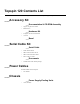
Topspin 120 Contents List The following contents are included with your Topspin 120 product: ___Accessory Kit ___Documentation & CD-ROM Assembly • Topspin 120 Quick Start Guide • Release Notes ___Hardware Kit • 2 Topspin 120 rack-mount brackets • 12 screws ___Bezel ___Serial Cable Kit ___Serial Cable • Serial cable document • DB-9 connector male to RJ-45 • DB-9 connector female to RJ-45 • MX-9-1 roll-over cable ___Documents • Located inside serial cable kit package ___Power Cables Locate
xi Product Registration THANK YOU FOR PURCHASING YOUR TOPSPIN® PRODUCT Topspin Communications is pleased that you have selected Topspin for your computing infrastructure. Topspin provides comprehensive customer support resources via telephone and Web access. Topspin’s Customer Support Website has the latest TopspinOS (IB Switch and I/O Chassis Operating System), Linux and Windows Host Side Drivers, Boot over Infiniband Firmware and technical documentation.
xii • Email: support@topspin.com • Phone: (800) 499-1473 • Online Help Desk: http://support.topspin.
xiii Terms and Conditions of Sale for Topspin Communications, Inc. PLEASE READ THESE TERMS AND CONDITIONS CAREFULLY BEFORE USING THE PRODUCTS THAT ARE PROVIDED WITH THIS AGREEMENT. BY USING ANY PRODUCTS, YOU ACKNOWLEDGE THAT YOU HAVE READ AND UNDERSTOOD ALL THESE TERMS AND CONDITIONS AND YOU WILL BE CONSENTING TO BE BOUND BY THEM.
xiv price or subsequently invoiced to the Customer. In the event Topspin is required to pay any such tax, duty or charge, Customer will promptly reimburse Topspin. 3. Payment/Financing. Topspin will determine Customer's credit terms on a per-order basis and such terms are subject to a credit review and approval by Topspin in its sole discretion. The amount of credit may be changed or credit withdrawn by Topspin at anytime in its sole discretion. All payments shall be made in U.S.
xv Customer must provide written notice to Topspin within thirty (30) days of delivery in the event that Products do not conform to the quotation made by Topspin. 6. Intellectual Property Rights.
xvi STATES/JURISDICTIONS DO NOT ALLOW THE EXCLUSION OF IMPLIED WARRANTIES SO THE ABOVE EXCLUSIONS MAY NOT APPLY TO CUSTOMER. TOPSPIN'S LIMITED WARRANTY GIVES CUSTOMER SPECIFIC LEGAL RIGHTS. CUSTOMER MAY ALSO HAVE OTHER RIGHTS, WHICH VARY FROM STATE/JURISDICTION TO STATE/JURISDICTION. 10. Confidentiality.
xvii assign or delegate this Agreement or any rights or obligations hereunder, whether voluntarily, by operation of law or otherwise, without the prior written consent of Topspin (except as expressly set forth in Section 4(f)). Topspin may assign this Agreement to any successor by way of merger, acquisition or sale of all or substantially all of assets relating to this Agreement. Topspin or any successor may assign all of part of the right to payments under this Agreement.
xviii
xix Topspin Limited End User Warranty Topspin provides the following limited warranty (“Limited Warranty”) for Topspin products: • For a period of (1) year from the date of shipment, the hardware components will be free from defects in materials and workmanship; and • For a period of ninety (90) days from the date of shipment, the software components will substantially conform to Topspin’s then-current specifications. Products may be registered at www.topspin.
xx How to Obtain Warranty Service To obtain warranty service, the product must first be registered with Topspin as outlined above. Topspin must be notified during the applicable warranty period in order to have any obligation under the Limited Warranty. To request warranty service, you must contact Topspin’s service department. Contact information can be obtained form Topspin’s Web site at www.topspin.com/support.
xxi Declaration of Conformity Topspin Communications, Inc. 515 Ellis St. Mountain View, CA 94043 Phone: (650) 316-3300 Fax: (650) 316-3269 http://www.topspin.
xxii
1 1 Topspin 120 Quick Start The following sections appear in this chapter: • “Prepare the Site” on page 1 • “Mount the Chassis in a Rack” on page 1 • “Configure Basic Connectivity” on page 6 • “Configure and Connect InfiniBand Hosts” on page 7 Prepare the Site Read the cautionary statements in “Safety Information” on page v. Register the InfiniBand system online. Go to http://topspin.com/support/. Ground yourself using an approved ground wrist-strap.
2 • Any associated mounting clips to secure the brackets to your rack (2 for each rail of the rack) • A rack with enough clearance for the Topspin 120 switch and cables. • Two people are recommeded to perform the installation Rack Mount Installation To mount the Topspin 120 chassis in a rack, perform the following steps: 1. Open the Topspin 120 box. 2. Remove the chassis, rack brackets, CD-ROM, parts bag, and documentation. 3. Place the chassis on a secure, clean surface. 4.
3 The standard method is to face the flange toward the front of the chassis. However, you can also mount the flange toward the back if you want to mount the switch backward in the chassis (service-side forward). flange Figure 1-2: Attaching One Rail to Switch Chassis 3. Repeat Step 1. and Step 2. on the opposite side of the switch chassis. The two counterparts to these sliding rails (without screw holes) should still be unattached. 4. Check your rack for clearance for the switch.
4 5. Attach the remaining 2 rail brackets to your rack. a. Orient a rack bracket toward the back of the rack bracket with the flange facing away from the rack. The flange should go around the outside of your rack post, as shown in Figure 1-3. NOTE: (Note: If you are mounting the switch backward, the rack bracket should be installed to the front of the rack). b. Secure the rack brackets with your screws through the back of the rack, as shown in Figure 1-4. c. Repeat on both sides of the rack.
5 8. Secure the switch with your screws through the front of the rack, as show in Figure 1-6. Figure 1-6: Secure switch with screws through the front of the rack Installing the Switch with Two People The following method of installation requires two people to mount the chassis into the rack. One person holds the switch while another person secures it to the rack. 1. Separate the assembled rack brackets.
6 4. Insert the switch into the rack with the rack brackets attached. You will have to tilt the switch unit to one side to avoid hitting the sides of the rack with the brackets as the pass around the back posts. Return the switch unit to a horizontal position once the switch is inside the rack. The rear rack brackets flanges should wrap around the outside of the back rack posts. 5. Have one person hold the switch while another person secures the switch to the rack. 6.
7 e. Enter the user name and password. The default user name is super, and the default password is super. f. Enter the enable command. g. Enter the configure command. Login: super Password: super Topspin-120> Topspin-120> enable Topspin-120 # Topspin-120 # configure Topspin-120(config)# h. Enter the interface mgmt-ethernet command to enter config-if-mgmt-ethernet mode.. Topspin-120(config)# interface mgmt-ethernet Topspin-120(config-if-mgmt-ethernet)# i.
8 An integrated suite of drivers is provided, including IPoIB, SRP, SDP, uDAPL and MPI . a. Make sure your Linux kernel is supported. Contact the Technical Support website at http://www.topspin.com/support/ b. Insert the supplied CD-ROM into the CD-ROM drive. The CD-ROM is provided in the box with the Switched Computing system. c. (Optional) Mount the file-system for the CD-ROM drive if your platform does not auto-mount devices. d.
9 5. Plug InfiniBand cables from the host to the InfiniBand switch. a. To plug in an InfiniBand cable, push the connector into the interface until you hear/feel a click. b. Wiggle your connector back and forth and pull gently to be sure that both sides of the connector have locked firmly into place.
10 NOTE: If your host does not provide an ample amount of free space around a given IB port, double-check that your IB cable connector engages fully. Wiggle your connector back and forth to be sure that both sides of the connector have locked firmly into place. c. To remove a cable with a pinch connector, pinch both sides of the back of the connector and pull the connector away from the port. Figure 1-12: Removing a Pinch Connector d.
11 (Optional) Launch the Chassis Manager Chassis Manager is a web-based GUI that can be used to manage a single InfiniBand chassis. Prepare Your Device To launch Chassis Manager on your Topspin 270, you must: • Configure an IP address on the Ethernet management port, if you have not already done so. • Configure an IP gateway on the Ethernet management port, if you have not already done so. • Optional. Enable Telnet services (Telnet services should be enabled by default).
12 4. Type the Management IP address of your Server Switch in the address field of your browser and press Enter. Figure 1-14: Web Browser Window A log-in window opens. Figure 1-15 displays the log-in window. Figure 1-15: Chassis Manager Log-In Window 5. Enter your Server Switch user name and password in the log-in window and click the OK button. Chassis Manager loads in your browser window.
13 (Optional) Install the Element Manager GUI For more information regarding the Element Manager tasks, refer to the InfiniBand User Guide. 1. Check that you have sufficient system resources. You will need: • 32 MB free RAM • 50 MB disk space + 50MB additional temporary space during installation • 300 Mhz processor • 800x600 screen resolution, 16bit color depth 2. Insert the Topspin CD-ROM into the CD-ROM drive of a server that has network access to a Topspin management port. 3.
14
Index C chassis manager launch 11 D declaration of conformity xxi E element manager install 13 H HTTP 11 HTTPs 11 I install java GUI 13 ip http server 11 J java GUI install 13 system resources 13 L launching Chassis Manager 11 P prepare your switch 11 prerequisites 11 product registration xi R register product xi registration instructions xi S safety information v setup 11 starting Chassis Manager 11 switch configuration 11 T telnet enable 11 W web GUI launch 11