Configuring LAN Interfaces Use the information in this chapter to configure LAN interfaces supported on Cisco routers and access servers.
Configuring LAN Interfaces Configuring an Ethernet or Fast Ethernet Interface With the Catalyst 3000 or Catalyst 5000 system, the Fast Ethernet processor can be used to aggregate up to twelve 10-Mbps LANs and give them high-speed access to such Layer 3 routing services as providing firewalls and maintaining access lists. Cisco 7200 series routers support an I/O controller with an RJ-45 interface.
Configuring LAN Interfaces Configuring an Ethernet or Fast Ethernet Interface Specifying an Ethernet or Fast Ethernet Interface To specify an Ethernet interface and enter interface configuration mode, use one of the following commands in global configuration mode: Command Purpose interface ethernet number Begins interface configuration. interface ethernet slot/port Begins interface configuration for the Cisco 7200 and Cisco 7500 series routers.
Configuring LAN Interfaces Configuring an Ethernet or Fast Ethernet Interface Specifying Full-Duplex Operation The default is half-duplex mode on the FEIP2-DSW-2FX. To enable full-duplex mode on the FEIP2-DSW-2FX (for a maximum aggregate bandwidth of 200 Mbps), use either of the following commands in interface configuration mode: Command Purpose full-duplex Enables full-duplex on the Fast Ethernet interface of the FEIP2-DSW-2FX.
Configuring LAN Interfaces Configuring an Ethernet or Fast Ethernet Interface Extending the 10BASE-T Capability On a Cisco 4000 series or Cisco 4500 series routers, you can extend the twisted-pair 10BASE-T capability beyond the standard 100 meters by reducing the squelch (signal cutoff time). This feature applies only to the LANCE controller 10BASE-T interfaces. LANCE is the AMD controller chip for the Cisco 4000 and Cisco 4500 Ethernet interface. Note Does not apply to the Fast Ethernet interface.
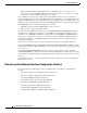
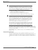
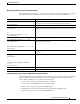
Configuring LAN Interfaces Configuring an Ethernet or Fast Ethernet Interface Table 3 Relationship Between Duplex and Speed Command Options Duplex Command Speed Command Resulting System Actions duplex auto speed auto Autonegotiates both speed and duplex modes. duplex auto speed 100 duplex half speed auto Autonegotiates both speed and duplex modes. duplex half speed 10 Forces 10 Mbps and half duplex. duplex full speed 10 Forces 10 Mbps and full duplex.
Configuring LAN Interfaces Configuring an Ethernet or Fast Ethernet Interface Note If you use the full-duplex and the half-duplex commands to change the transmission mode of the first two PA-12E/2FE interfaces (port 0 and port 1), the transmission speed of the two PA-12E/2FE interfaces automatically defaults to 100-Mbps.
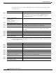
Configuring LAN Interfaces Configuring an Ethernet or Fast Ethernet Interface To configure the interfaces on the PA-12E/2FE port adapter, use the following commands in global configuration mode: Step 1 Command Purpose bridge bridge-group protocol ieee Specifies the type of Spanning-Tree Protocol. The PA-12E/2FE port adapter supports DEC and IEEE Spanning-Tree Protocols; however, we recommend using the IEEE protocol when configuring bridge groups.
Configuring LAN Interfaces Configuring an Ethernet or Fast Ethernet Interface Monitoring and Maintaining the PA-12E/2FE Port Adapter After configuring the new interface, you can display its status and verify other information. To display information about the PA-12E/2FE port adapter, use the following commands in EXEC mode: Command Purpose show version Displays the configuration of the system hardware, the software version, the names and sources of configuration files, and the boot image.
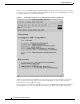
Configuring LAN Interfaces Configuring an Ethernet or Fast Ethernet Interface You can access the 12E/2FE VLAN Configuration WebTool from your router’s home page. For complete procedures on how to use the VLAN Configuration WebTool, refer to the PA-12E/2FE Ethernet Switch Port Adapter book that accompanies the hardware. Figure 2 Example Home Page for a Cisco 7200 Series Router (Cisco 7206 Shown) All Cisco routers running Cisco IOS Release 11.0 or later have a home page.
Configuring LAN Interfaces Configuring Fast EtherChannel Configuring the 100VG-AnyLAN Port Adapter The 100VG-AnyLAN port adapter (PA-100VG) is available on Cisco 7200 series routers and on Cisco 7500 series routers. The PA-100VG provides a single interface compatible with and specified by IEEE 802.12 to support 100 Mbps over Category 3 or Category 5 unshielded twisted-pair (UTP) cable with RJ-45 terminators. The PA-100VG supports 802.3 Ethernet packets and can be monitored with the IEEE 802.
Configuring LAN Interfaces Configuring Fast EtherChannel links. Unicast, broadcast, and multicast traffic is distributed across the links providing higher performance and redundant parallel paths. In the event of a link failure, traffic is redirected to remaining links within the Fast EtherChannel without user intervention. In this release of the Fast EtherChannel feature, IP traffic is distributed over the port-channel interface while traffic from other routing protocols is sent over a single link.
Configuring LAN Interfaces Configuring Fast EtherChannel Configuring the Port-Channel Interface To configure the port-channel interface, use the following commands beginning in global configuration mode: Command Purpose Step 1 interface port-channel channel-number Creates the port-channel interface and enters interface configuration mode. The channel number can be 1 to 4. Step 2 ip address ip-address mask Assigns an IP address and subnet mask to the Fast EtherChannel.
Configuring LAN Interfaces Configuring Fast EtherChannel Configuring the Fast Ethernet Interfaces To assign the Fast Ethernet interfaces to the Fast EtherChannel, use the following commands beginning in global configuration mode: Command Purpose Step 1 interface fastethernet slot/port-adapter/port Creates or modifies an existing Fast Ethernet interface and enters interface configuration mode.
Configuring LAN Interfaces Configuring a Fiber Distributed Data Interface EtherChannel even if the line protocol goes down. This can result in unpredictable behavior. The implementation of the Port Aggregation Protocol in a subsequent release of this feature will remove the dependency on keepalives. See the “LAN Interface Configuration Examples” section for configuration examples. You can monitor the status of the Fast EtherChannel interface by using the show interfaces port-channel EXEC command.
Configuring LAN Interfaces Configuring a Fiber Distributed Data Interface The scatter-gather architecture used by particle-based switching provides the following advantages: • Allows drivers to use memory more efficiently (especially when using media that has a large maximum transmission unit [MTU]). For example, Token Ring buffers could be 512 bytes rather than 16 KB. • Allows concurrent use of the same region of memory.
Configuring LAN Interfaces Configuring a Fiber Distributed Data Interface The CFM state is through A in the sample output, which means this interface’s Phy-A has successfully completed CMT with the Phy-B of the neighbor and Phy-B of this interface has successfully completed CMT with the Phy-A of the neighbor. The display (or nondisplay) of the upstream and downstream neighbor does not affect the ability to route data.
Configuring LAN Interfaces Configuring a Fiber Distributed Data Interface Enabling FDDI Bridging Encapsulation Cisco FDDI by default uses the SNAP encapsulation format defined in RFC 1042. It is not necessary to define an encapsulation method for this interface when using the FIP.
Configuring LAN Interfaces Configuring a Fiber Distributed Data Interface Setting the Token Rotation Time You can set the FDDI token rotation time to control ring scheduling during normal operation and to detect and recover from serious ring error situations. To do so, use the following command in interface configuration mode: Command Purpose fddi token-rotation-time microseconds Sets the FDDI token rotation time.
Configuring LAN Interfaces Configuring a Fiber Distributed Data Interface Modifying the TB-Min Timer You can change the TB-Min timer in the PCM from its default value of 100 ms. To do so, use the following command in interface configuration mode: Command Purpose fddi tb-min milliseconds Sets TB-Min timer in the PCM. Modifying the FDDI Timeout Timer You can change the FDDI timeout timer in the PCM from its default value of 100 ms.
Configuring LAN Interfaces Configuring a Fiber Distributed Data Interface Controlling the CMT Microcode You can control whether the CMT onboard functions are on or off. The FIP provides CMT functions in microcode. These functions are separate from those provided on the processor card and are accessed through EXEC commands. The default is for the FIP CMT functions to be on. A typical reason to disable is when you work with new FDDI equipment and have problems bringing up the ring.
Configuring LAN Interfaces Configuring a Hub Interface Controlling the FDDI SMT Message Queue Size You can set the maximum number of unprocessed FDDI Station Management (SMT) frames that will be held for processing. Setting this number is useful if the router you are configuring gets bursts of messages arriving faster than the router can process them.
Configuring LAN Interfaces Configuring a Hub Interface Enabling a Hub Port To enable a hub port, use the following commands in global configuration mode: Command Purpose Step 1 hub ethernet number port [end-port] Specifies the hub number and the hub port (or range of hub ports) and enters hub configuration mode. Step 2 no shutdown Enables the hub ports.
Configuring LAN Interfaces Configuring a Hub Interface To enable the link test function on a hub port connected to an Ethernet interface, use the following command in hub configuration mode: Command Purpose link-test Enables the link test function. Enabling Source Address Control On an Ethernet hub port only, you can configure a security measure such that the port accepts packets only from a specific MAC address.
Configuring LAN Interfaces Configuring a LAN Extender Interface Configuring a LAN Extender Interface The Cisco 1001 and Cisco 1002 LAN Extenders are two-port chassis that connect a remote Ethernet LAN to a core router at a central site (see Figure 3). The LAN Extender is intended for small networks at remote sites.
Configuring LAN Interfaces Configuring a LAN Extender Interface Expanded View of Cisco 1000 Series LAN Extender Connection Remote LAN Other networks Core Router LEX A Serial LAN Extender B Ethernet S2979 Figure 4 Virtual Ethernet connection Management of the LAN Extender Interface Although there is a physical connection between the core router and the LAN Extender, what you actually manage is a remote Ethernet LAN.
Configuring LAN Interfaces Configuring a LAN Extender Interface Configuring the LAN Extender You configure the LAN Extender from the core router—either a Cisco 4000 series or Cisco 7000 series router—as if it were simply a network interface board. The LAN Extender cannot be managed or configured from the remote Ethernet LAN or via a Telnet session.
Configuring LAN Interfaces Configuring a LAN Extender Interface LAN Extender Interface Configuration Task List To configure a LAN Extender interface, perform the tasks described in the following sections: • Configuring and Creating a LAN Extender Interface (Required) • Defining Packet Filters (Optional) • Controlling Priority Queueing (Optional) • Controlling the Sending of Commands to the LAN Extender (Optional) • Shutting Down and Restarting the LAN Extender’s Ethernet Interface (Optional) • R
Configuring LAN Interfaces Configuring a LAN Extender Interface Note Do not configure the MTU to a value other than the default value when you are configuring a LAN Extender interface. Defining Packet Filters You can configure specific administrative filters that filter frames based on their source MAC address. The LAN Extender forwards packets between a remote LAN and a core router.
Configuring LAN Interfaces Configuring a LAN Extender Interface The major reason to create access lists on a LAN Extender interface is to prevent traffic that is local to the remote Ethernet LAN from traversing the WAN and reaching the core router. You can filter packets by MAC address, including vendor code, and by Ethernet type code.
Configuring LAN Interfaces Configuring a LAN Extender Interface Once you have defined an access list to filter by a particular vendor code, you can assign this list to a particular LAN Extender interface so that the interface will then filter based on the MAC source addresses of packets received on that LAN Extender interface.
Configuring LAN Interfaces Configuring a LAN Extender Interface To control priority queueing on a LAN Extender interface, perform the following tasks: • Set the priority by protocol type. • Assign a priority group to an interface. To establish queueing priorities based on the protocol type, use one of the following commands in global configuration mode: Command Purpose priority-list list protocol protocol {high | medium | normal | low} Establishes queueing priorities based on the protocol type.
Configuring LAN Interfaces Configuring a LAN Extender Interface Shutting Down and Restarting the LAN Extender’s Ethernet Interface From the core router, you can shut down the LAN Extender’s Ethernet interface. This stops traffic on the remote Ethernet LAN from reaching the core router, but leaves the LAN Extender interface that you created intact. Note There are no commands that allow you to shut down the serial interface on the LAN Extender.
Configuring LAN Interfaces Configuring a LAN Extender Interface Troubleshooting the LAN Extender The primary means of troubleshooting the LAN Extender is by using the light emitting diodes (LEDs) that are present on the chassis. This section will help you assist the remote user at the LAN Extender site who can observe the LEDs. The key to problem solving is to try to isolate the problem to a specific subsystem.
Configuring LAN Interfaces Configuring a LAN Extender Interface Table 4 LED Trouble Indicators (continued) SYSTEM OK On Steady Lights when the unit passes the power on diagnostics. This indicates proper operation. Blinking Blinks while running startup diagnostics, then goes on steady. Blinking after the start-up diagnostics indicates that a system error has been encountered. Contact your system administrator who will have you disconnect and then reconnect the power to recycle your LAN Extender.
Configuring LAN Interfaces Configuring a Token Ring Interface Configuring a Token Ring Interface Cisco supports various Token Ring interfaces. Refer to the Cisco Product Catalog for information about platform and hardware compatibility. The Token Ring interface supports both routing (Layer 3 switching) and source-route bridging (Layer 2 switching) on a per-protocol basis. For example, IP traffic could be routed while SNA traffic is bridged. Routing features enhance source-route bridges.
Configuring LAN Interfaces Configuring a Token Ring Interface Dedicated Token Ring Port Adapter The Dedicated Token Ring port adapter (PA-4R-DTR) is available on Cisco 7500 series routers, Cisco 7200 series routers, and Cisco 7000 series routers with the 7000 Series Route Switch Processor (RSP7000) and 7000 Series Chassis Interface (RSP7000CI). The PA-4R-DTR provides up to four IBM Token Ring or IEEE 802.5 Token Ring interfaces.
Configuring LAN Interfaces LAN Interface Configuration Examples Configuring PCbus Token Ring Interface Management The Token Ring interface on the AccessPro PC card can be managed by a remote LAN manager over the PCbus interface. Currently, the LanOptics Hub Networking Management software running on an IBM-compatible PC is supported.
Configuring LAN Interfaces LAN Interface Configuration Examples Ethernet Encapsulation Enablement Example These commands enable standard Ethernet Version 2.
Configuring LAN Interfaces LAN Interface Configuration Examples Router(config)# interface ethernet 3/2 Router(config-if)# bridge-group 20 Router(config-if)# cut-through Router(config-if)# no shutdown Router(config-if)# exit Router(config)# %LINEPROTO-5-UPDOWN: Line protocol on Interface Ethernet3/2, changed state to up %LINK-3-UPDOWN: Interface Ethernet3/2, changed state to up Router(config)# interface ethernet 3/3 Router(config-if)# bridge-group 20 Router(config-if)# cut-through Router(config-if)# no shut
Configuring LAN Interfaces LAN Interface Configuration Examples Fast EtherChannel Configuration Examples Figure 10 shows four point-to-point Fast Ethernet interfaces that are aggregated into a single Fast EtherChannel interface.
Configuring LAN Interfaces LAN Interface Configuration Examples The following is a partial example of a configuration file. The MAC address is automatically added to the Fast Ethernet interface when the interfaces are added to the Fast EtherChannel. Note If you do not assign a static MAC address on the port-channel interface, the Cisco IOS software automatically assigns a MAC address. If you assign a static MAC address and then later remove it, the Cisco IOS software automatically assigns a MAC address.
Configuring LAN Interfaces LAN Interface Configuration Examples Hub Configuration Examples The following sections provide examples of hub configuration: • Hub Port Startup Examples • Source Address for an Ethernet Hub Port Configuration Examples • Hub Port Shutdown Examples • SNMP Illegal Address Trap Enablement for Hub Port Example Hub Port Startup Examples The following example configures port 1 on hub 0 of Ethernet interface 0: hub ethernet 0 1 no shutdown The following example configures ports
Configuring LAN Interfaces LAN Interface Configuration Examples SNMP Illegal Address Trap Enablement for Hub Port Example The following example specifies the gateway IP address and enables an SNMP trap to be issued to the host 172.69.40.51 when a MAC address violation is detected on hub ports 2, 3, or 4. It specifies that interface Ethernet 0 is the source for all traps on the router. The community string is defined as the string public and the read/write parameter is set. ip route 0.0.0.0 0.0.0.0 172.22.
Configuring LAN Interfaces LAN Interface Configuration Examples Ethernet Type Code Filtering Example Using the same configuration as in the previous section, you could allow only the Macintosh traffic by Ethernet type code with the following access list: access-list 220 permit 0x809B 0x0000 interface lex 0 lex input-type-list 220 This access list permits only those messages whose protocol number matches the masked protocol number in the first line.
Configuring LAN Interfaces LAN Interface Configuration Examples Cisco IOS Interface Configuration Guide IC-68