
Installation Guide


When installing DC power to the AP, always connect the AP end of the cable FIRST. When removing
the DC power connector, always disconnect the AP end of the cable LAST.
Caution
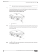
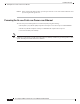
Step 3 Remove the cap from the DC connector located on the right side of the AP. Push inward toward the AP and
turn counterclockwise about a ¼ turn. The cap should dis-engage from the bayonet thread on the 2-pin DC
connector. Do not discard the cap unless you are sure the port will never need to be sealed in the future. See
the following image for the location of the DC power connector.
Figure 48: Position of the DC Power-In Port on the Right Side of the AP
DC Connector Cap1
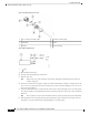
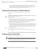
Step 4 Insert DC supply 2-pin connector into plug located on the left side of the AP. Position and orient the plug to
align with the keyed pins on the connector. Push inward toward the AP until the connector body rotates and
clicks into place. The plug is a bayonet-style. It should automatically lock into place when pushed inward.
Figure 49: Installing the DC plug
2-Pin DC plug1
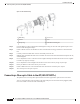
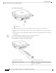
Step 5 If the AP is to be power with customer supplied DC source. The following steps show how to terminate the
Cisco-supplied DC plug to the cable.
Cisco Catalyst 9124AX Series Outdoor Access Point Hardware Installation Guide
53
Installation Overview
Connecting a DC Power Cable to the Access Point