
Installation Guide


To reduce the risk of fire, use only No. 24 AWG or larger telecommunication line cord.
Statement 1023
Danger
The installer is responsible for ensuring that powering the AP from this type of power injector is
allowed by local and/or national safety and telecommunications equipment standards.
Note
Step 4 Ensure that the antennas are connected, and that ground is attached to the AP before you apply power to the
AP.
Step 5 Connect a shielded outdoor-rated Ethernet (CAT5e or better) cable between the power injector and the AP's
PoE-in connector.
Step 6 Connect the Ethernet cable to the AP PoE-In port. See Connecting an Ethernet Cable to the Access Point , on
page 55.
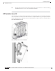
Connecting a DC Power Cable to the Access Point
You can purchase the AC/DC power adapter AIR-PWRADPT-RGD2= that comes with a 2-pin DC plug
pre-installed. If you supply DC power using your own DC supply, you need to use the DC plug kit supplied
with the AIR-ACC-KIT1= accessory kit.
When powering the AP with DC power, you must ensure that DC power can be conveniently removed from
the unit. The power should not be removed by disconnecting the DC power connector on the unit
Connect the unit only to a DC power source that complies with the safety extra-low voltage (SELV)
requirements in IEC 60950 based safety standards. Statement 1033
Danger
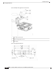
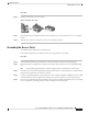
To connect a DC power cable, you need to supply these tools and material:
• Cisco orderable option DC power supply (AIR-PWRADPT-RGD2=) with an attached 2-pin connector
or Two-pin DC power connector (supplied with Cisco AIR-ACC-KIT1= kit)
• Shielded outdoor-rated DC power cable (18 AWG) with outside cable diameter of 0.20 to 0.35 inch (0.51
to 0.89 cm)
• Adjustable or open-end wrench
• Hex crimp tool: 0.10 inch (2.54-mm)
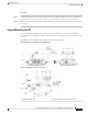
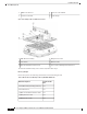
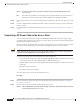
To connect the DC power cable to the AP, follow these steps:
Procedure
Step 1 Before connecting DC power to the AP, ensure that the ground is connected to the AP. See Grounding the
Access Point, on page 49.
Step 2 Turn off all power sources to the AP, including the DC power source.
This unit might have more than one power supply connection. All connections must be removed
to de-energize the unit. Statement 1028
Danger
Cisco Catalyst 9124AX Series Outdoor Access Point Hardware Installation Guide
52
Installation Overview
Connecting a DC Power Cable to the Access Point