
Installation Guide
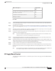

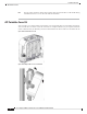


NotesPoE-outGbE
PHY
SPF
Module
Ethernetm
Gig
AUX
Radio
dBmRadio
1
dBmRadio 0PoE-in/DC
Input
SKU
Chillwave5-GHz
Primary radio
2.4-GHz radio
Serving
radios
disabled
NNN1Genabled–
disabled–disabled.3afC9124AXI
C9124AXD
Dual
Radio
mode
-NYN1Genabled232x2232x2.3at
With
802.3bt or
UPOE
input,
limit
PoE-out to
7.0W
7WYY2.5Genabled244x4244x4.3bt /
UPOE
PoE
output is
802.3af
compliant
15.4WYY2.5Genabled244x4244x4DC
input
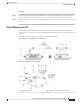
Connecting a Power Injector
The AP supports the following power injectors:
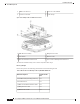
Table 12: Supporting Power Injectors
DescriptionPower Source
60W rated outdoor power injector, with North America AC plugAIR-PWRINJ-60RGD1=
60W rated outdoor power injector, global version without AC plugAIR-PWRINJ-60RGD2=
30W rated single-port PoE injectorAIR-PWRINJ6=
The power injector provides DC voltage to the AP over the Ethernet cable and supports a total end-to-end
Ethernet cable length of 100 m (328 ft) from the switch to the AP.
When an optional power injector powers your AP, follow these steps to complete the installation:
Procedure
Step 1 Before applying PoE to the AP, ensure that the AP is grounded (see Grounding the Access Point, on page
49).
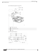
Step 2 Identify the components needed for the installation, see the Typical Access Point Installation Components,
on page 18.
Step 3 Connect a CAT5e or better Ethernet cable from your wired LAN network to the power injector.
Cisco Catalyst 9124AX Series Outdoor Access Point Hardware Installation Guide
51
Installation Overview
Connecting a Power Injector