
Installation Guide
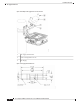

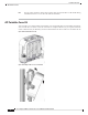
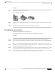


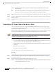

Figure 47: Position of the Ground Pad on the Right Side of the AP
Ground pad, where the ground strap screw holes are located.1
Powering the Access Point
The AP supports these power sources:
• DC power – 24–56 VDC
• Power-over-Ethernet (PoE)
The AP can be powered via the PoE input from an inline power injector or a suitably powered switch port.
Depending on the configuration and regulatory domain, the required power for full operation is 802.3bt or
UPOE.
The supporting outdoor power injectors are AIR-PWRINJ-60RGD1 and AIR-PWRINJ-60RGD2 rated at 60W
each. These power injectors support 10/100/1000BASE-T operation only. They do not support the 2.5GBAST-T
(mGig) Ethernet speed.
Note
Table 11: Cisco Catalyst 9124AX AP Reduced Power Feature Matrix
NotesPoE-outGbE
PHY
SPF
Module
Ethernetm
Gig
AUX
Radio
dBmRadio
1
dBmRadio 0PoE-in/DC
Input
SKU
Per
Path
SSPer
Path
SS
Cisco Catalyst 9124AX Series Outdoor Access Point Hardware Installation Guide
50
Installation Overview
Powering the Access Point