
Installation Guide
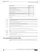
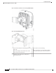
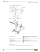
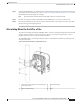
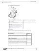
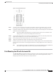
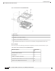

Figure 36: L-bracket AP mount dimensions
Step 2 Use four screws and, if required, wall anchors to attach the L-bracket to the mounting surface. You must
procure these screws and anchors, and they must follow local codes to support at least 50 lbs (22.7 kg.)
Step 3 Position the AP horizontally against the L-bracket's bottom to align the four mounting holes on the AP’s back
with the slots in the mounting bracket.
The AP has additional mounting holes to be positioned and located to best accommodate on site
cabling. Ensure to review before mounting the AP to the bracket.
Note
Step 4 Screw an M6 x12–mm bolt into each of the four support bolt holes on the back of the AP by hand. Do not
tighten the bolt completely. Leave it loose to slide in the bracket slot.
Step 5 Ensure that the AP and all attached cables have clearance to install and provide drip loops.
Step 6 Tighten the four M6 bolts to 40–lbf-in (4.5 Nm) torque using a 10–mm wrench.
Step 7 Position and install the solar shield on top of the L-bracket and AP. Align four holes in the shield to mount
holes in AP. Insert four #8-32 screws through the shield into AP. Torque tighten the screws to 15 lbf-in (17
kgf-cm).
We recommend you install the solar shield. However, if the AP's installed location is shaded from
the sun (For example: indoors or under an eave), the solar shield is not required.
Note
Pole Mounting the AP with Horizontal Kit
The AIR-MNT-HORZ1= mounting kit contains a mounting L-bracket and components for both pole mounting
and wall mounting. Using this kit, you can install the AP on a pole or mast. It supports metal, wood, or
fiberglass poles from 2 to 5 inches (51 to 127 mm) in diameter.
Cisco Catalyst 9124AX Series Outdoor Access Point Hardware Installation Guide
41
Installation Overview
Pole Mounting the AP with Horizontal Kit