
Installation Guide
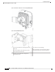
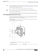

Step 6 Using the 90 mm M8 long screw and the hardware supplied with the pivoting bracket, bolt the AP and bracket
plate to the wall plate mounted on the wall. See Figure 30: Pivoting Wall Mounting Bracket , on page 34 for
this assembly. Do not fully tighten the assembly.
The AP should be mounted with the status LED on the base facing downwards.
Note
Step 7 Pivot the AP as required, and then fully tighten the 90 mm M8 long screw using a 13–mm wrench.
Step 8 Proceed with installing antennas (only for external antenna models), connecting the data cables, grounding
the AP, powering, and configuring the AP.
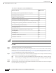
Articulating Mount for the AP to a Pole
The optional articulating mounting kit AIR-MNT-ART1= contains a pivoting mounting bracket for both wall
and pole mounting. This kit can be used to install the AP on a pole or mast. It supports metal, wood, or
fiberglass poles from 2 to 5 inch (51 to 127mm) in diameter.
The AIR-MNT-ART1= articulating mounting kit allows for adjusting the AP position by pivoting the AP
along its vertical plane.
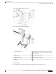
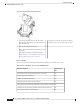
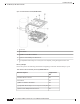
Figure 33: AP Pole Mounted Using the Pivoting Mounting Bracket
Steel band clamps3One of four mounting holes for mounting the
AP to the bracket
1
Pole4Slots for band clamps2
Cisco Catalyst 9124AX Series Outdoor Access Point Hardware Installation Guide
37
Installation Overview
Articulating Mount for the AP to a Pole