
Installation Guide
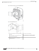
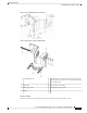
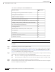
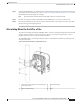
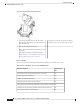
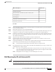
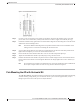
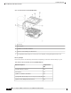

Table 6: Materials for Mounting AP to a Wall with AIR-MNT-ART1= Kit
Supplied in the
Kit?
Materials Needed
YesGround lug and screws (provided with the access point)
YesPivoting mount kit and hardware
Yes(8) M6 x 12-mm Hex-head Bolts
YesAdapter bracket for option horizontal mount
YesTwo stainless steel band clamps (adjustable 2 to 5 inch (51 to 127 mm)
NoCrimping tool for ground lug, Panduit CT-720 with CD-720-1 die
NoFour wall mounting screws (6 mm max)
No#6 AWG ground wire
NoShielded outdoor-rated Ethernet (CAT5e or better) cable
NoGrounding block
NoGrounding rod
No13-mm box-end wrench or socket set
No10-mm box-end wrench
The mounting surface, attaching screws, and optional wall anchors to support a 50 lb (22.7 kg) static weight.
Caution
Procedure
Step 1 Disassemble the pivot kit, if not already disassembled.
Step 2 Use the mounting bracket's wall-plate end as a template to mark four screw hole locations on the mounting
surface. See Figure 30: Pivoting Wall Mounting Bracket , on page 34 for the mounting bracket screw hole
locations (screw holes of maximum 6 mm). See Figure 31: Pivoting Wall Mounting Bracket Dimensions, on
page 35 for the dimensions of the pivoting mounting bracket.
Step 3 Use four screws and, if required, wall anchors to attach the mounting bracket's wall-plate end to the mounting
surface. These screws and anchors are to be sourced independently.
You can use an exterior-grade plywood backboard to mount the AP to stucco, cement, or drywall.
Note
The mounting wall, attaching screws, and wall anchors must support a 50-lb (22.7 kg) static weight.
Note
Step 4 Align the AP-plate end of the bracket with the screw holes in the AP's back.
Step 5 Fasten the bracket plate to the AP by using four M6 x12 mm bolts and a 10–mm box or socket wrench. Tighten
the bolts to 40 lbf-in (4.5 Nm) of torque.
Cisco Catalyst 9124AX Series Outdoor Access Point Hardware Installation Guide
36
Installation Overview
Articulating Mount for the AP to a Wall