
Installation Guide


PurposeAP Mounting Kit
3
Pivoted mounting kit for both vertical and horizontal mounting,
on wall and for pole of diameter 2 to 5 inch (51 to 127 mm). See:
Articulating Mount for the AP to a Wall, on page 33
Articulating Mount for the AP to a Pole, on page 37
AIR-MNT-ART1=
Fixed mounting kit, allowing mounting the AP to mounted
horizontal to the ground. Horizontal mount to a wall or for pole
of diameter 2 to 5 inch (51mm to 127 mm). See:
Pole Mounting the AP with Horizontal Kit, on page 41
Wall Mounting the AP with Horizontal Kit, on page 39
Optional AIR-ACC-PS-MNT1 kit to mount DC power supply.
See:
DC Supply Mount Bracket, on page 43
AIR-MNT-HORZ1=AIR-ACC-PS-MNT1
(Optional)
Cable strand horizontal mount. See:
Strand Mounting the AP, on page 45
AIR-MNT-STRAND1=
3
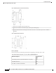
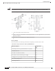
Mount the AP using no less than four screw holes on a bracket.
• When mounting an AP vertically, ensure that the AP is oriented with the LED indicators pointing down.
• Mount the AP in such a way that all antenna ports and the console port are visible and accessible for
future use.
• Align the AP’s omnidirectional antennas vertical to the ground.
• Align the AP’s directional antenna such that the main beam is parallel to or tilted down toward the
horizon.
Note
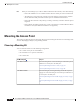
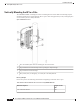
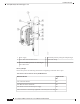
Vertically Mounting the AP to a Wall
The AIR-MNT-VERT1= mounting kit contains a mounting bracket for wall mounting or pole mounting.
You can use the mounting bracket as a template to mark the mounting holes' positions for your installation,
install the mounting bracket, and then attach the AP to the bracket.
The mounting wall, attaching screws, and wall anchors must support a 50-lb (22.7–kg) static weight.
Caution
Cisco Catalyst 9124AX Series Outdoor Access Point Hardware Installation Guide
25
Installation Overview
Vertically Mounting the AP to a Wall