Gigabit Route Processor Installation and Configuration Note Product Numbers: GRP-B=, GRP= Document Order Number: DOC-784339= This hardware installation and configuration note describes the Gigabit Route Processor (GRP), the route processor for use in Cisco 12000 Series Routers.
Important Information Important Information This section contains information about the following hardware and software requirements: • Router Information • Cisco IOS Software Requirements • Product Overview Router Information For hardware installation and maintenance information on Cisco 12000 Series Routers, refer to the installation and configuration guide for your router. This includes information on card slot locations and other general requirements.
Product Overview Cisco IOS Software Requirements For software configuration information, refer to the Cisco IOS software configuration and command reference publications for the installed Cisco IOS Release. Also refer to the Cisco IOS software release notes for additional information. The GRP line card is supported in Cisco IOS Release 11.2(9)GS and later. GRP configurations with 512 MB of route memory are only compatible with Product Number GRP-B=. Cisco IOS Release 12.0(19)S or 12.
Product Overview • Providing an auxiliary port for other external equipment (such as modems) • Providing an IEEE 802.
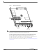
Product Overview Figure 2 GRP (Horizontal Orientation) Backplane connector U42 Bank 2 DRAM DIMMs Bank 1 U39 Flash SIMM EJ EC T -1 OT SL -0 OT SL RE SE CO T X AU LIN PCMCIA slots slot 0: bottom slot 1: top Note K Auxiliary port Console port TX LL RX RJ M II -4 H10547 U17 5 GIGABIT ROUTE PROCESSOR Alphanumeric LED displays Ethernet interface (RJ-45 or MII) The onboard Flash memory (called bootflash) contains the Cisco IOS software boot image, and a Flash memory card or Flash d
Product Overview Memory Components Figure 2 shows the locations of the various types of memory used on the GRP. GRP memory component types are presented in the following sections: • DRAM • SRAM • NVRAM • Flash Memory Their functions are presented in Table 1.
Product Overview Caution To prevent memory problems, DRAM DIMMs must be +3.3VDC, 60-nanosecond (ns) EDO devices. Do not attempt to install other devices in the DIMM sockets. Cisco recommends that you use Cisco-approved memory options. (See Table 14 on page 49.
Product Overview System Status LEDs The two types of system status LEDs used on the GRP. • Status LEDs • Display LEDs Status LEDs The GRP has the following eight status LEDs: • 2 PCMCIA activity LEDs (one LED per PCMCIA slot)—Each LED goes on when its PCMCIA slot is accessed. The LEDs receive power from the switched slot voltage. • 4 RJ-45 Ethernet port LEDs—These LEDs are used in conjunction with the RJ-45 Ethernet connector. When the MII Ethernet port is in use, the LEDs are disabled.
Product Overview Flash Card Slots The GRP includes two Flash card slots. Either slot can support an ATA Flash disk or a linear Flash memory card. Note The GRP only supports +5VDC Flash card devices. It does not support +3.3VDC Flash card devices. All combinations of different Flash card devices are supported by the GRP. You can use ATA Flash disks, linear Flash memory cards, or a combination of the two. Each slot has an ejector button for ejecting a card from the slot.
Preparing for Installation Preparing for Installation Installation preparation is presented in the following sections: • Safety Guidelines • Translated Safety Warnings and Agency Approvals • Electromagnetic Compatibility Regulatory Statements • Preventing Electrostatic Discharge • Working with Electrical Equipment • Required Tools and Parts Safety Guidelines Before you perform any procedure in this publication, review the safety guidelines in this section to avoid injuring yourself or damaging
Preparing for Installation Electromagnetic Compatibility Regulatory Statements FCC Class A Compliance This equipment has been tested and found to comply with the limits for a Class A digital device, pursuant to part 15 of the FCC rules. These limits are designed to provide reasonable protection against harmful interference when the equipment is operated in a commercial environment.
Preparing for Installation Class A Notice for Hungary Warning This equipment is a class A product and should be used and installed properly according to the Hungarian EMC Class A requirements (MSZEN55022). Class A equipment is designed for typical commercial establishments for which special conditions of installation and protection distance are used.
Preparing for Installation Class A Notice for Korea Warning This is a Class A Device and is registered for EMC requirements for industrial use. The seller or buyer should be aware of this. If this type was sold or purchased by mistake, it should be replaced with a residential-use type. Statement 294 Preventing Electrostatic Discharge Electrostatic discharge (ESD) damage, which can occur when electronic cards or components are improperly handled, results in complete or intermittent failures.
Replacing a GRP Required Tools and Parts You need the following tools and parts to remove and replace a GRP. If you need additional equipment, contact a Cisco customer service representative for ordering information. • 3/16-inch flat-blade screwdriver for the captive installation screws that secure the GRP in its slot. • ESD-prevention equipment or the disposable ESD-preventive wrist strap included with all spares and upgrade kits. • Antistatic mat, foam pad, or bag for the removed GRP.
Replacing a GRP Figure 3 GRP Ejector Levers, Captive Installation Screws, and Upper Card Cage Slots (Cisco 12012 Shown) Ejector lever and captive screw 0 R E IE KT TIV RR P AC CA RX EJ EC T 1 OTSL 0 OT- SL 1 0 ET 0 X AU RES CR IT IC AL OR OR IN MAJ M R E IE ELL TIV RR C AC CA RX R E IE ELL TIV RR C AC CA RX R E IE KT TIV RR P AC CA RX 2 OLE NS CO AC R E IE KT TIV RR P AC CA RX T O/L Alarm card slot ALARM 1 3 LIN LL X R TX CO R E IE KT TIV RR P AC CA RX K Upper card cage slot 0 MII
Replacing a GRP Figure 4 Ejector Levers and Captive Installation Screw (Cisco 12012 shown) Loosen captive screws b Pivot ejector levers away from card to unseat card 0 a R VE IE T TI RR PK AC CA RX T EC EJ -1 OT SL -0 OT SL 0 0 X 1 AU T SE RE R AL JOR NO IC IT MA MI CR R VE IE LL TI RR CE AC CA RX R VE IE LL TI RR CE AC CA RX R VE IE T TI RR PK AC CA RX NS 2 CO OL E EJ EC T LT O/ AC R VE IE T TI RR PK AC CA RX -1 OT SL -0 OT SL SE T X AU RE ALARM 1 3 TX LL CO RX R VE IE T TI
Replacing a GRP Step 7 Place the removed GRP on an antistatic mat or foam. If you plan to return the GRP to the factory, immediately place it in an antistatic bag to prevent ESD damage. Installing a GRP When you install a GRP, be sure to use the ejector levers, which help to ensure that the GRP is fully inserted in the backplane connector. (See Figure 3.
Replacing a GRP Connecting to the Console Port The system console port on the GRP is a DCE DB-25 receptacle for connecting a data terminal, which you must configure. The console port is labeled Console, as shown in Figure 5. Before connecting the console port, check your terminal’s documentation to determine the baud rate of the terminal you plan to use. The baud rate of the terminal must match the default baud rate (9600 baud).
Replacing a GRP Connecting to the Auxiliary Port The auxiliary port on the GRP is an EIA/TIA-232 DTE, DB-25 plug for connecting a modem or other DCE device (such as a CSU/DSU or another router) to the router. The port is labeled Auxiliary. An example of a modem connection is shown in Figure 5. The asynchronous auxiliary port supports hardware flow control and modem control. Table 3 lists the pinout for this port.
Replacing a GRP RJ-45 Receptacle and Plug (Horizontal Orientation) 87654321 RJ-45 receptacle Warning Category 5, UTP cable with plug H11096 Figure 6 The ports labeled Ethernet, 10BASE-T, Token Ring, Console, and AUX are safety extra-low voltage (SELV) circuits. SELV circuits should only be connected to other SELV circuits. Because the basic rate interface (BRI) circuits are treated like telephone-network voltage, avoid connecting the SELV circuit to the telephone network voltage (TNV) circuits.
Replacing a GRP MII Connections The MII connection requires an external physical sublayer (PHY) and an external transceiver. Depending on the type of media you use between the MII connection on the GRP and your switch or hub, the network side of your 100BASE-T transceiver should be appropriately equipped—with SC-type or ST-type connectors (for optical fiber), BNC connectors, and so forth. Figure 9 shows the pin orientation of the female MII receptacle on GRP.
Replacing a GRP Table 6 lists the cabling specifications for 100-Mbps transmission over unshielded twisted-pair (UTP) and shielded twisted-pair (STP) cables. Note At the auto-sensed data transmission rate of 100 Mbps, the Ethernet port provides maximum usable bandwidth that is less than 100 Mbps; a maximum usable bandwidth of approximately 20 Mbps can be expected if you use either the MII or RJ-45 connection.
Replacing a GRP • MII connections—Attach an MII cable directly to the MII receptacle on the GRP or attach a 100BASET transceiver with the media appropriate to your application to the MII port on the GRP. (See Figure 10.) Be sure to use the appropriate strain relief on cable connections. • RJ-45 connections—Attach the Category 5 UTP cable directly to the RJ-45 receptacle on the GRP. (See Figure 10.
GRP Boot Process Overview Figure 11 Using the Ethernet Port on the GRP Network 1.0.0.0 Router A (Cisco 12000 series) Host A EO POS Host B Network 2.0.0.0 EO Router B (Cisco 7500 series) Router C (Cisco 7500 series) S6755 Host A GRP Boot Process Overview The following sequence describes a typical GRP boot process: 1. System power is turned on. 2. MBus module receives +5 VDC and starts executing MBus software. 3.
Starting the System and Observing Initial Conditions For AC-input power supplies, the green AC OK LED should go on. For DC-input power supplies, the green input OK LED should go on. For both types of power supplies, the output fail LED should be off. Step 2 Listen for the system blower modules or fan trays in the router; you should immediately hear them operating. In a noisy environment, place your hand in front of the exhaust vents to verify that the blower modules are operating.
Starting the System and Observing Initial Conditions Step 4 During the line card boot process, which occurs immediately after the GRP boots, observe the alphanumeric display LEDs on each line card. The system attempts to boot identical line cards in parallel. Furthermore, the system boots line cards as soon as they are powered on and become available for a system boot. (The physical location of the alphanumeric display LEDs on the line cards is the same as on the GRP, which is shown in Figure 12.
Verifying Interface Status On the console screen, after the system displays the system banner and hardware configuration, the following System Configuration Dialog prompt appears: --- System Configuration Dialog --At any point you may enter a question mark '?' for help. Use ctrl-c to abort configuration dialog at any prompt. Default settings are in square brackets '[]'.
Configuring the Ethernet Interface Figure 13 GRP LEDs (Partial Front Panel View) T EC EJ -1 OT SL -0 OT SL T SE RE X AU K LIN LL CO TX 5 -4 RJ H10762 RX I MI Configuring the Ethernet Interface The IEEE 802.3 Ethernet interface, located on the GRP, allows connections to external Ethernet networks and is capable of data transmission rates of 10 Mbps and 100 Mbps.
Configuring the Ethernet Interface • Using Configuration Mode to Configure the Ethernet Interface, page 29 • Using the setup Command Facility to Configure the Ethernet Interface, page 29 Using Configuration Mode to Configure the Ethernet Interface Use the following procedure to perform a basic configuration of the Ethernet interface in configuration mode: Step 1 At the privileged-level prompt, enter configuration mode and specify that the console terminal is the source of the configuration subcommands
Implementing Additional Configuration and Maintenance Tasks (Additional displayed text omitted from this example.) Configuring interface Ethernet0: Is this interface in use?: yes Configure IP on this interface?: yes IP address for this interface: 3.3.1.1 Number of bits in subnet field: 8 Class A network is 3.0.0.0, 8 subnet bits; mask is 255.255.0.
Implementing Additional Configuration and Maintenance Tasks Table 9 Software Configuration Register Bit Descriptions Bit 1 Hexadecimal Description 00 to 03 0x0000 to 0x000F Boot field (see Table 10) 06 0x0040 System software ignores NVRAM contents 07 0x0080 OEM2 bit enabled 08 0x0100 Break disabled 09 0x0200 Use secondary bootstrap 10 0x0400 IP3 broadcast with all zeros 11 to 12 0x0800 to 0x1000 Console line speed (default is 9600 baud) 13 0x2000 Boot default Flash software if n
Implementing Additional Configuration and Maintenance Tasks You can enter the boot command only, or include additional boot instructions with the command such as the name of a file stored in Flash memory or a file that you specify for booting from a network server. If you use the boot command without specifying a file or any other boot instructions, the system boots from the default Flash image (the first image in onboard Flash memory).
Implementing Additional Configuration and Maintenance Tasks Step 5 Display the configuration register value currently in effect, which will be used at the next reload by entering the show version EXEC command. The value is displayed on the last line of the screen display, as in the following example: Configuration register is 0x141 (will be 0x2102 at next reload) Step 6 Save your settings.
Implementing Additional Configuration and Maintenance Tasks Table 11 Default Boot Filenames (continued) Action/File Name Bit 3 Bit 2 Bit 1 Bit 0 cisco4-GRP 0 1 0 0 cisco5-GRP 0 1 0 1 cisco6-GRP 0 1 1 0 cisco7-GRP 0 1 1 1 cisco10-GRP 1 0 0 0 cisco11-GRP 1 0 0 1 cisco12-GRP 1 0 1 0 cisco13-GRP 1 0 1 1 cisco14-GRP 1 1 0 0 cisco15-GRP 1 1 0 1 cisco16-GRP 1 1 1 0 cisco17-GRP 1 1 1 1 Bit 8 controls the console Break key.
Implementing Additional Configuration and Maintenance Tasks Table 13 System Console Terminal Transmission Rate Settings (continued) Baud Bit 12 Bit 11 2400 1 1 1200 1 0 Bit 13 determines the server response to a bootload failure. Setting bit 13 causes the server to load operating software from Flash memory after five unsuccessful attempts to load a boot file from the network. Clearing bit 13 causes the server to continue attempting to load a boot file from the network indefinitely.
Implementing Additional Configuration and Maintenance Tasks Figure 14 Installing and Removing Flash Memory Card or Flash Disk a T EC EJ -1 OT SL -0 OT SL b SE T X AU RE T EC EJ c -1 OT SL -0 OT SL T SE X AU RE T EC EJ -1 OT SL -0 OT SL H10703 T SE X AU RE Both slots can be used at the same time.
Implementing Additional Configuration and Maintenance Tasks Caution The Flash memory card or Flash disk does not insert all the way inside the GRP; a portion of the card remains outside of the slot. Do not attempt to force the card past this point. Use the following procedure to remove a Flash memory card or Flash disk: Step 1 To eject the card, press the ejector button until the card is free of the connector at the back of the slot. (See Figure 14c.
Implementing Additional Configuration and Maintenance Tasks Caution The following formatting procedure erases all information on the Flash memory card or Flash disk. To prevent the loss of important data that might be stored on a Flash memory card or Flash disk, proceed carefully. If you want to save the data on a Flash memory card or Flash disk, copy the data to a server before you format the card.
Implementing Additional Configuration and Maintenance Tasks Specifying Cisco IOS Image Used to Boot the System Use the following series of commands to specify that a Cisco IOS software image is bootable. (In this example, the file is named new.image.) Note that because the configuration register must be set to 0x2102, the config-register command is part of the sequence. Router# config terminal Router(config)# no boot system Router(config)# boot system flash slot0:new.
Implementing Additional Configuration and Maintenance Tasks You can delete a file from any Flash memory media using the delete filename command, where filename is any file within Flash memory.
Implementing Additional Configuration and Maintenance Tasks Enter configuration commands, one per line. End with CTRL-Z. Router(config)#config-reg 0x2102 Router(config)#boot system disk0:gsr-p-mz.120-17.S Router(config)#^Z Router#copy running-config startup-config Copying Files to Flash Memory Copying a new Cisco IOS software image to Flash memory might be required whenever a new Cisco IOS software release or maintenance release becomes available.
Implementing Additional Configuration and Maintenance Tasks Copying a Cisco IOS Software Image into Flash Memory Card or Flash Disk You can copy a Cisco IOS software image into Flash memory; however, you must first format the Flash memory card or Flash disk and make the image in the Flash memory card or Flash disk bootable.
Implementing Additional Configuration and Maintenance Tasks Copying Cisco IOS Software Images Between Flash Memory Cards or Flash Disks As future releases of Cisco IOS software become available, you will receive these images either as a file booted from a network server, a file on floppy disk, or a file on a Flash memory card or Flash disk.
Implementing Additional Configuration and Maintenance Tasks Step 5 Use the following series of commands to designate the file image.new (in the Flash memory card or Flash disk in slot 0) as the default boot image: Router# config t Router(config)# no boot system Router(config)# boot system flash slot0:image.new Crtl-z Router# copy running-config startup-config Router# reload When the system reloads, it will boot the file image.new from the Flash memory card or Flash disk in slot 0.
Implementing Additional Configuration and Maintenance Tasks Step 2 Enter the copy startup-config slot0:filename command as follows: Router# copy startup-config slot0:myfile2 20575008 bytes available on device slot0, proceed? [confirm] Address or name of remote host [1.1.1.1]? Loading new.image from 1.1.1.
Implementing Additional Configuration and Maintenance Tasks Step 1 Use the copy running-config slot0:filename command as follows: Router# copy running-config slot0:myfile2 20575008 bytes available on device slot0, proceed? [confirm] Address or name of remote host [1.1.1.1]? Loading new.image from 1.1.1.
Implementing Additional Configuration and Maintenance Tasks Recovering from Locked Blocks in Flash Memory Cards or Flash Disks A locked block in Flash memory cards or Flash disks occurs when power is lost, or a Flash memory card or Flash disk is unplugged during a write or erase operation. When a block of Flash memory is locked, it cannot be written to or erased, and the operation will consistently fail at a particular block location.
Implementing Additional Configuration and Maintenance Tasks Step 6 Set the configuration register to ignore the configuration file information as follows: rommon 1> confreg Configuration Summary enabled are: console baud: 9600 boot: image specified by the boot system command or default to: cisco2-GRP do you enable enable enable enable enable enable change change wish to change the configuration? y/n [n]: y “diagnostic mode”? y/n [n]: “use net in IP bcast address”? y/n [n]: “load rom after netbootfails”?
Implementing Additional Configuration and Maintenance Tasks Change it to a value of 0x2102 (factory default) using the config-register 0x value command. Step 13 Enter Ctrl-Z to exit configuration mode. Step 14 Reboot the router and enable it using the recovered password. Upgrading GRP Memory This section provides the procedure for increasing the amount of extended data output (EDO) DRAM on a GRP by replacing up to two dual in-line memory modules (DIMMs).
Implementing Additional Configuration and Maintenance Tasks Note Each GRP DIMM socket has one plastic lever on one end, which you use to remove the DIMM from its socket. (See Figure 16.) Before proceeding, ensure that you have the proper tools and ESD-prevention equipment available. To upgrade DRAM, you will install DIMMs in one or two banks (U39 and U42). Table 14 lists the various available configurations of DRAM DIMMs, the number of DIMMs for each configuration, and the DRAM banks they occupy.
Implementing Additional Configuration and Maintenance Tasks Removing DIMMs This section provides the procedure for removing DIMMs. As you remove DIMMs, place them on an antistatic mat or store them in an antistatic bag. You can use the DIMMs that you remove in other compatible equipment. Caution To prevent ESD damage, handle DIMMs by the card edges only. Use the following procedure to remove the existing DIMM(s): Step 1 Turn off the system power.
Implementing Additional Configuration and Maintenance Tasks Installing New DIMMs This section provides the procedure for installing new DIMMs. Caution To prevent system and memory problems when installing DRAM, make sure that the card’s DRAM DIMMS are +3.3VDC, 60-ns, EDO devices. Do not attempt to install other DRAM devices in the GRPs DIMM sockets. Caution DIMMs are sensitive components that can be shorted by mishandling; they are susceptible to ESD damage.
Obtaining Documentation Step 8 Caution Step 9 When the DIMM is installed, check that the release lever is flush against the side of the DIMM socket. If it is not, the DIMM might not be seated properly. If the DIMM appears misaligned, carefully remove it and reseat it in the socket. Push the DIMM firmly back into the socket until the release lever is flush against the side of the DIMM socket. When inserting DIMMs, use firm but not excessive pressure.
Documentation Feedback You can access the Cisco website at this URL: http://www.cisco.com International Cisco websites can be accessed from this URL: http://www.cisco.com/public/countries_languages.shtml Ordering Documentation You can find instructions for ordering documentation at this URL: http://www.cisco.com/univercd/cc/td/doc/es_inpck/pdi.htm You can order Cisco documentation in these ways: • Registered Cisco.
Obtaining Additional Publications and Information Accessing all the tools on the Cisco TAC website requires a Cisco.com user ID and password. If you have a valid service contract but do not have a login ID or password, register at this URL: http://tools.cisco.com/RPF/register/register.do Opening a TAC Case Using the online TAC Case Open Tool is the fastest way to open P3 and P4 cases. (P3 and P4 cases are those in which your network is minimally impaired or for which you require product information.
Obtaining Additional Publications and Information • The Cisco Product Catalog describes the networking products offered by Cisco Systems, as well as ordering and customer support services. Access the Cisco Product Catalog at this URL: http://cisco.com/univercd/cc/td/doc/pcat/ • Cisco Press publishes a wide range of general networking, training and certification titles. Both new and experienced users will benefit from these publications.