USER GUIDE 24-Port or 48-Port 10/100 + 4-Port Gigabit Smart Switch with Resilient Clustering Technology and PoE Model: SLM224G4PS, SLM248G4PS BUSINESS SERIES
About This Guide About This Guide Icon Descriptions While reading through the User Guide you may see various icons that call attention to specific items. Below is a description of these icons: NOTE: This check mark indicates that there is a note of interest and is something that you should pay special attention to while using the product. WARNING: This exclamation point indicates that there is a caution or warning and it is something that could damage your property or product.
Table of Contents Chapter 1: Introduction 1 Chapter 2: Product Overview 2 SLM248G4PS . . . . . . . . . . . . . . . . . . . . . . . . . . . . . . . . . . . . . . . . . . . . . . . . . 2 Front Panel . . . . . . . . . . . . . . . . . . . . . . . . . . . . . . . . . . . . . . . . . . . . . . . 2 Back Panel . . . . . . . . . . . . . . . . . . . . . . . . . . . . . . . . . . . .
Table of Contents Setup > Network Settings . . . . . . . . . . . . . . . . . . . . . . . . . . . . . . . . . . . . . 18 Setup > Time . . . . . . . . . . . . . . . . . . . . . . . . . . . . . . . . . . . . . . . . . . . . . 19 Setup > Stack Management . . . . . . . . . . . . . . . . . . . . . . . . . . . . . . . . . . . . 20 Port Management . . . . . . . . . . . . . . . . . .
Table of Contents SNMP > Group Membership . . . . . . . . . . . . . . . . . . . . . . . . . . . . . . . . . . . 41 SNMP > Communities . . . . . . . . . . . . . . . . . . . . . . . . . . . . . . . . . . . . . . . 41 SNMP > Notification Filter . . . . . . . . . . . . . . . . . . . . . . . . . . . . . . . . . . . . . 42 SNMP > Notification Recipient . . . . . . . . . . . . . . . . . .
Table of Contents Appendix C: Glossary 59 Appendix D: Specifications 63 Appendix E: Warranty Information 65 Exclusions and Limitations . . . . . . . . . . . . . . . . . . . . . . . . . . . . . . . . . . . . . . . 65 Obtaining Warranty Service . . . . . . . . . . . . . . . . . . . . . . . . . . . . . . . . . . . . . . . 65 Technical Support . . . . . . . . . . . . . . . . . . . . . . . . . . . . .
Chapter 1 Introduction Chapter 1: Introduction Thank you for choosing the Linksys 24/48-Port 10/100 + 4-Port Gigabit Smart Switch with Resilient Clustering Technology and PoE. These switches allow you to expand your network securely. User control is secured using 802.1x security using a RADIUS authentication mechanism and can also be controlled using MAC filtering. For Wireless or VoIP deployments, the SLM224G4PS and SLM248G4PS Switches support the IEEE802.
Chapter 2 Chapter 2: Product Overview SLM248G4PS Front Panel The Switch LEDs and ports are located on the front panel. Front Panel of the SLM248G4PS System (Green/Amber) Lights up green to indicate that the Switch is powered on. Lights up amber while the Switch is performing a system self-test. Blinks amber if the self-test fails.
Chapter 2 Back Panel The Console port and power port are located on the back panel of the Switch. Back Panel of the SLM248G4PS CONSOLE The Console port is a serial port that allows you to connect to a computer’s serial port (for configuration purposes) using the provided serial cable. You can use HyperTerminal to manage the Switch using the console port. POWER The Power port is where you connect the AC power. SLM224G4PS Front Panel The Switch’s LEDs and ports are located on the front panel.
Chapter 2 Product Overview SLM224G4PS Shared Port Mapping miniGBIC Port Standard Port miniGBIC 1 G3 miniGBIC 2 G4 Back Panel The Console port and power port are located on the back panel of the Switch. Back Panel of the SLM224G4PS CONSOLE The Console port is a serial port that allows you to connect to a computer’s serial port (for configuration purposes) using the provided serial cable. You can use HyperTerminal to manage the Switch using the console port.
Chapter 3 Installation Chapter 3: Installation Pre-Installation Considerations Fast Ethernet Considerations If you are using the Switch for Fast Ethernet (100 Mbps) applications, you must observe the following guidelines: Overview This chapter will explain how to connect network devices to the Switch. The following diagram shows a typical network configuration.
Chapter 3 Desktop Placement • Attach the rubber feet to the recessed areas on the bottom of the Switch. • Place the Switch on a desktop near an AC power source. • Keep enough ventilation space for the switch and check the environmental restrictions mentioned in the Specifications Appendix as you are placing the Switch. Installation To rack-mount the Switch in any standard 19-inch wide, 1U-high rack, follow the instructions described below. 1.
Chapter 3 For a 1000 Mbps device: • Connect a Category 5e Ethernet network cable to port G1, G2, G3, or G4 on the Switch. For a 10/100 Mbps PoE device: • SLM248G4PS: Connect a Category 5e Ethernet network cable to one of ports 1-12 or ports 25-36 on the Switch. • SLM224G4PS: Connect a Category 5e Ethernet network cable to one of ports 1-6 or ports 13-18 on the Switch. 3. Connect the other end of the network cable to a PC or other network device. 4. Repeat steps 2 and 3 to connect additional devices.
Chapter 3 Installation 1. Connect one end of a Category 5e Ethernet network cable to port G1 on Unit 1. 2. Connect the cable’s other end to port G2 on Unit 2. 3. Connect one end of a Category 5e Ethernet network cable to port G1 on Unit 2. 4. Connect the cable’s other end to port G2 on Unit 3. 5. Connect one end of a Category 5e Ethernet network cable to port G1 on Unit 3. 6. Connect the cable’s other end to port G2 on Unit 4. 7.
Chapter 4 Chapter 4: Configuration Using the Console Interface Overview Configuration Using the Console Interface 5. Set the serial port settings as follows, then click OK. Bits per Second: 38400 Databits: 8 Parity: None Stop bits: 1 Flow control: None The Switch features a menu-driven console interface that lets you perform basic switch configuration and easily manage your network.
Chapter 4 Configuration Using the Console Interface How to Use the Console Interface Switch Main Menu The Console Interface consists of a hierarchical series of menu screens and settings screens. Each menu displays a list of options. Selecting an option brings up a settings screen where you can configure the relevant settings. After successful login, the Main Menu screen appears.
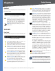
Chapter 4 Configuration Using the Console Interface System Information From the System Information screen you can check current firmware versions and other general switch information. General System Information Management Settings System Information The Management Settings screen displays the Serial Port Configuration option. Versions The Versions screen displays version-related information for each switch in the system.
Chapter 4 Configuration Using the Console Interface User & Password Settings Security Settings The User & Password Settings screen displays all the user accounts defined on the system. The IP Configuration screen displays one option: Disable Active Management Access Profile. User & Password Settings Security Settings The default account is admin. You cannot edit this account (its user name and password cannot be changed).
Chapter 4 Configuration Using the Console Interface IP Address Settings Network Configuration The IP Address Settings screen allows you to set the IP information for the Switch. The Network Configuration screen offers a choice of two tests, Ping and TraceRoute. IP Address Configuration Network Configuration IP Address This sets the Switch’s IP Address. The default setting is 192.168.1.254.
Chapter 4 After the traceroute test is complete, the TraceRoute screen displays the IP address, status, and statistics of the traceroute test. File Management The File Management screen allows you to upload or download files, such as the startup configuration, boot, or image file, using a TFTP server. Configuration Using the Console Interface Restore System Default Settings To restore the Switch back to the factory default settings, select Restore System Default Settings and press Enter.
Chapter 4 Configuration Using the Console Interface Unit The unit number of the switch, from 1 to 6. PoE Status MAC Address The MAC address of the switch. The PoE Status screen displays the following status information for each of the switch’s PoE ports: port number, port status, power allocation, and power consumption. This screen is read-only; to change a port’s PoE settings, use the Port Configuration screen. Software The version number of the software that runs the switch.
Chapter 4 Configuration Using the Console Interface PoE Settings Help The PoE Settingsscreen allows you to change a PoE port’s PoE settings. You can set a PoE port’s priority, or enable or disable PoE on a PoE port. The Help screen explains how to navigate the various screens of the console interface. Help PoE Settings Logout System Mode The System Mode screen displays information about the system mode: Select Logout to log out of the console interface.
Chapter 5 Chapter 5: Configuration Using the Web-based Utility This chapter describes the features included in the Webbased Utility. All features shown in this chapter, unless specifically identified, are included in the all of Stackable Switches. Unique features for specific Switches are noted. NOTE: The web-based utility is optimized for a screen resolution of 1024 x 768. Internet Explorer version 5.5 or above is required. To use the utility, open your web browser, enter http://192.168.1.
Chapter 5 Default Gateway The IP address (default 0.0.0.0) of the gateway router between the Switch and management stations on other network segments. This setting can be configured from the Setup tab’s Network Settings screen. NOTE: The Default Gateway cannot be configured if the system IP address is set to 192.168.1.254. (The system IP Address is set using Setup > Network Settings.) Configuration Using the Web-based Utility Setup > Zoom The Zoom screen depicts the status of all the ports in the system.
Chapter 5 Configuration Using the Web-based Utility System Location This is used to enter a description of where the Switch is physically located, such as 3rd Floor. System Contact Enter the name of the administrator responsible for the system. System Object ID This is used for SNMP purposes and is set to 1.3.6.1.4.1.3955.6.5.224(248).2. Base MAC Address Displays the Switch’s physical address. IP Configuration Management VLAN This drop-down menu allows you to select the Management VLAN.
Chapter 5 • Recurring If daylight saving time has fixed start and end dates, check this box and fill in these fields: • From Specify the day, week, month, and time when daylight saving time will be enabled. • To Specify the day, week, month, and time when dalight saving time will be disabled. SNTP Servers This is where you configure a Simple Network Time Protocol (SNTP) server. SNTP servers are used to set the system time and date automatically at set intervals.
Chapter 5 Speed The port’s configured rate in Mbps. Duplex The port’s current duplex mode, Half or Full. MDI/MDIX The port’s MDI/MDIX type. The MDI setting is used if the port is connected to an end station. The MDIX setting is used if the port is connected to a hub or another switch. Flow Control This is the flow control status of the port. It is active when the port uses Full Duplex Mode. Type Displays the port type. LAG This indicates if the port belongs to a LAG.
Chapter 5 Neighbor Advertisement (Read-only) The speed and duplex mode settings that the neighbor port (the port to which the selected port is connected) is advertising. If the port has no neighbor port, this field displays “Unknown.” Back Pressure Select Enable or Disable (default) to enable or disable Back Pressure mode on the port. Current Back Pressure (Read-only) The current Back Pressure mode on the port.
Chapter 5 Administrative Status The LAG’s administrative status. Select either Up or Down to enable or disable the LAG. Current Status (Read-only) The LAG’s status, either Up or Down. Admin Auto Negotiation Select Enable (default) or Disable to enable or disable Auto-Negotiation on the LAG. Auto-Negotiation allows a LAG to advertise its transmission rate, duplex mode, and flow control settings to other LAGs. Current Auto Negotiation (Read-only) The LAG’s current Auto-Negotiation status.
Chapter 5 Port The port whose PoE settings are being configured. To configure a different port, select it from the drop-down menu. Admin Status/Enable This indicates if PoE is enabled or disabled on the port. To enable PoE on the port, keep the default, Enable (option selected). To disable PoE on the port, unselect the Enable option. Configuration Using the Web-based Utility VLAN ID ID of the VLAN being configured (2-4093, no leading zeroes). VLAN Name Name of the VLAN (1 to 32 characters).
Chapter 5 Ingress Filtering Enables or disables Ingress filtering on the port. Ingress filtering discards packets that do not match port ingress rules. The default is Enabled. LAG Displays the LAG, if any, to which the port belongs. A port’s LAG settings override the VLAN port settings. Click Save Changes to save your changes, or click Cancel Changes to cancel. VLAN Management > Port to VLAN You use the Port to VLAN screen to add ports to a VLAN and delete ports from a VLAN.
Chapter 5 Remove To remove the port from a VLAN, select the VLAN from the list on the right and click Remove. The VLAN ID will appear in the list on the left without the “T” or “U”. Tagging When you are adding a port to a VLAN, specify whether the port is Tagged (default) or Untagged. Click Save to save your changes and leave the screen open, Save & Close to save your changes and close the screen, or click Close to close the screen without saving your changes.
Chapter 5 Configuration Using the Web-based Utility RMON History Table Statistics > RMON History RMON History Source Interface Indicates the interface from which the history samples were taken. To specify the interface, select Unit No. (default) and specify the unit number and port from the drop-down menus, or select LAG and select the LAG number from the drop-down menu. Sampling Interval Indicates (in seconds) how often samples are taken from the ports. The range is 1 to 3600.
Chapter 5 Configuration Using the Web-based Utility Oversize Packets Displays the number of oversized packets (over 1518 octets) received on the interface since the device was last refreshed. • Delta Subtracts the last sampled value from the Fragments Displays the number of fragments (packets with less than 64 octets, excluding framing bits, but including FCS octets) received on the interface since the device was last refreshed.
Chapter 5 Configuration Using the Web-based Utility Statistics > RMON Events The RMON Events screen is used to define RMON events. Statistics > Port Utilization Statistics > RMON Events Add Event Event Entry Displays the event. Community Displays the community to which the event belongs. Unit No The number of the unit that you are managing. Refresh Rate Select the rate at which to refresh the statistics display: No Refresh (default), 15 sec, 30 sec, or 60 sec.
Chapter 5 Configuration Using the Web-based Utility • Unicast Packets Displays the number of Unicast packets received on the selected interface. • Multicast Packets Displays the number of Multicast packets received on the selected interface. • Broadcast Packets Displays the number of Broadcast packets received on the selected interface. • Packets with Errors Displays the number of error packets received from the selected interface.
Chapter 5 Configuration Using the Web-based Utility Setting Timer The Setting Timer screen appears when you click Setting Timer on the 802.1x Settings screen. You use the Setting Timer screen to configure a port’s 802.1x functionality. Security > Port Security Security > 802.1x Settings > Setting Timer Port Displays the port name. Reauthentication Period Specifies the number of seconds after which a connected client must be reauthenticated. The range is 300 to 4294967295 seconds.
Chapter 5 Max Entries Specifies the number of MAC addresses that can be learned on the port. This field is enabled only if Learning Mode is set to Limited Dynamic Lock. The default value is 1. Action on Violation Indicates the action to be applied to packets arriving on a locked port. The possible values are: • Discard Discards packets from any unlearned source. This is the default value. • Forward Forwards packets from an unknown source without learning the MAC address.
Chapter 5 Configuration Using the Web-based Utility Broadcast Control Select the checkbox to apply Broadcast control on the selected interface. Broadcast control limits the amount of Broadcast packet types to be forwarded. The default is not selected (disabled). Mode Specifies the Broadcast mode currently enabled on the device. The possible values are: • Multicast & Broadcast Counts Multicast traffic together. Broadcast and • Broadcast Only Counts only Broadcast traffic.
Chapter 5 • The assignment of network traffic to a particular hardware queue • The assignment of internal resources • Traffic shaping The terms Class of Service (CoS) and QoS are used in the following context: • CoS provides varying Layer 2 traffic services. CoS refers to classifying traffic into traffic classes, where each class is handled as an aggregate whole, with no per-flow settings. CoS is usually related to the 802.
Chapter 5 QoS > DSCP Settings Configuration Using the Web-based Utility Interface The interface for which the queue shaping information is displayed. Either select Unit No and select the unit number and port from the drop-down menus, or select LAG and select the LAG number from the dropdown menu. Enable Ingress Rate Limit Status Indicates if rate limiting is defined on the interface. Enable Egress Shaping Rate Indicates if rate limiting is enabled on the interface.
Chapter 5 Spanning Tree Spanning Tree Protocol (STP) provides tree topography for any arrangement of bridges. STP also provides one path between end stations on a network, eliminating loops. Loops occur when alternate routes exist between hosts. Loops in an extended network can cause bridges to forward traffic indefinitely, resulting in increased traffic and reducing network efficiency. Configuration Using the Web-based Utility Root Forward delay (sec) The device forward delay time.
Chapter 5 Bridge Settings Priority Specifies the bridge priority value. When switches or bridges are running STP, each is assigned a priority. After exchanging BPDUs, the device with the lowest priority value becomes the Root Bridge. The default value is 32768. The value must be a multiple of 4096. For example, 4096, 8192, 12288, etc. The range is 0 to 65535. Hello Time Specifies the device Hello Time (the amount of time in seconds a root bridge waits between configuration messages).
Chapter 5 Multicast Multicast configuration options include IGMP Snooping, Bridge Multicast, and Bridge Multicast Forward All. Multicast > IGMP Snooping Configuration Using the Web-based Utility Host Timeout Indicates the amount of time host waits to receive a message before timing out. The default time is 260 seconds. MRouter Timeout Indicates the amount of the time the Multicast router waits to receive a message before it times out. The default value is 300 seconds.
Chapter 5 Configuration Using the Web-based Utility Enable Bridge Multicast Filtering Select this option to TBD. The default is disabled. Interface, Gigabit, LAG Lists switch interfaces and LAGs that can be added to a Multicast service. The configuration options are as follows: • Static Indicates the port is user-defined. • Dynamic Indicates dynamically.
Chapter 5 Use Default Uses the device generated Engine ID. The default Engine ID is based on the device MAC address and is defined per standard as: • First 4 octets First bit = 1, the rest is IANA Enterprise number. • Fifth octet Set to 3 to indicate the MAC address that follows. • Last 6 octets MAC address of the device. Configuration Using the Web-based Utility Click Add to List to add the Views configuration to the Views Table at the bottom of the screen.
Chapter 5 SNMP > Group Membership The Group Membership screen provides information for assigning SNMP access control privileges to SNMP groups. Configuration Using the Web-based Utility If both privacy and authentication are required, 32 bytes are defined. Each byte in hexadecimal character strings is two hexadecimal digits. Each byte can be separated by a period or a colon. Privacy Key Defines the Privacy Key (LSB). If only authentication is required, 20 bytes are defined.
Chapter 5 • Read Write Management access is read-write and changes can be made to the device configuration, but not to the community. • SNMP Admin User can access all device configuration options, and can modify the community. View Name Contains a list of user-defined SNMP views. Advanced Enables SNMP Advanced mode for a selected community and contains the following fields: Group Name Defines advanced SNMP communities group names.
Chapter 5 Configuration Using the Web-based Utility Notification Type Defines the notification sent. The possible field values are: Admin > User Authentication • Traps Indicates traps are sent. • Informs Indicates informs are sent. SNMPv1,2 Enables SNMPv1,2 as the Notification Recipient. Either SNMPv1,2 or SNMPv3 can be enabled at any one time, but not both at the same time.
Chapter 5 not displayed). You use this table to edit or delete existing user names and/or passwords, as described below. Create a new user name Make sure no entry is selected in the Local Users Table. If one is selected, click Cancel. Enter the new user name in the User Name field, and the password in the Password and Confirm Password fields. Then click Add to List to add a new entry to the Local Users Table. Change a password Highlight the associated user name in the Local Users Table.
Chapter 5 Address Aging Specifies the amount of time (in seconds) that a MAC address remains in the Dynamic MAC Address table before it times out, if no traffic from the source is detected. The default value is 300 seconds. Clear Table If selected, this clears the MAC Address table. Query Configuration Using the Web-based Utility Target Port The port that will mirror the traffic on the source port. Source Port The port whose traffic will be monitored.
Chapter 5 Configuration Using the Web-based Utility Admin > Save Configuration Admin > Cable Test - Gigabit Ports Advanced (Gigabit ports only) Click the Advanced button to open the Copper Cable Extended Feature screen. The Copper Cable Extended Feature screen contains the following fields. • Cable Status Displays the cable status. • Speed Indicates the speed at which the cable is transmitting packets. • Link Status Displays the current link status. • Pair The pair of cables under test.
Chapter 5 Configuration Using the Web-based Utility Admin > Firmware Upgrade Admin > Reboot Admin > Firmware Upgrade The Firmware Upgrade screen allows you to download firmware upgrade files from a TFTP server, or from your computer via the HTTP interface. Via TFTP Select this to download from or upload to a TFTP server. When you select this option, the following fields are displayed. • UPGRADE Select this option to upgrade the switch from a file located on a TFTP server.
Chapter 5 Configuration Using the Web-based Utility Admin > Logging Admin > Server Logs Admin > Logging The System Logs allow you to view device events in real time, and recording the events for later usage. System Logs record and manage events and report errors or informational messages. Event messages have a unique format, as per the SYSLOG protocols recommended message format for all error reporting.
Chapter 5 Configuration Using the Web-based Utility Severity Displays the log severity. Description Displays the log message text. Clear Logs Click this button to clear the logs. Admin > Flash Logs The Flash Log screen contains information about log entries saved to the Log File in flash memory, including the time the log was generated, the log severity, and a description of the log message. The Message Log is available after reboot. Admin > Flash Logs Log Index Displays the log number.
Appendix A About Gigabit Ethernet and Fiber Optic Cabling Appendix A: About Gigabit Ethernet and Fiber Optic Cabling Gigabit Ethernet Gigabit Ethernet runs at speeds of 1Gbps (Gigabit per second), ten times faster than 100Mbps Fast Ethernet, but it still integrates seamlessly with 100Mbps Fast Ethernet hardware. Users can connect Gigabit Ethernet hardware with either fiber optic cabling or copper Category 5e cabling, with fiber optics more suited for network backbones.
Appendix B Appendix B: About Switch Stacking A switch may operate in one of two modes: Stack or Standalone. You can select either mode during software boot or using the web-based utility’s Setup > Summary screen, with the new mode taking effect after the unit is reset. The factory default is Stack mode. Standalone Mode A switch operating in Standalone mode runs as an independent, single unit. All ports of a standalone switch operate as normal Ethernet links.
Appendix B the Console port, Telnet or Web-based Utility) and reset the units to make this assignment permanent. The unit that is assigned number 1 will act as the Master; this is indicated by the Stack Master LED on its front panel being lit amber. The unit that is assigned number 2 will act as the Backup Master. Stack Resiliency A stack’s topology may be either Ring or Chain.
Appendix B Stack Units Startup Process Whenever a unit in stack mode is initialized (powered up or rebooted) it goes through the same exact process, consisting of the following three steps: 1. Master Discovery/Election. 2. Unit ID allocation by the Master (including duplicate Unit ID conflict resolution) 3. Unit/port configuration by the Master About Switch Stacking ID was originally assigned automatically or manually. (Such units are called Master-enabled units).
Appendix B • If both duplicate units are in auto (self ordering) mode, then the unit ID will be decided by the Mac address. The unit with the lower Mac will keep its unit ID. The other will be reassigned a new unit ID. • If one of the duplicates is in auto (self ordering) mode and the other unit is in manual mode then the manual mode unit will keep its ID and the other will be reassigned a new unit ID. • If both duplicate units are in manual mode then both of them will be shut down.
Appendix B • If the incoming unit did not have an assigned Unit ID (that is, it was in factory default mode), it will be assigned the lowest available Unit ID by the Master. It is strongly recommended that automatic assigned unit ID mode be used since it provides better resiliency to the stack.
Appendix B • If the incoming unit already has an assigned Unit ID, and that Unit ID is unused in the current stack, the incoming unit will keep its assigned Unit ID and the Master will apply to it any configuration relevant to that Unit ID.
Appendix B before the split. Since the Backup Master was not acting as a master prior to the split, it will initiate a topology database and port-learning process. Traffic might be halted for a short period of time until synchronization (unit and port configuration) is completed. New units learned by the Backup Master will notify the system administrator (using SYSLOG messages and SNMP traps). d.
Appendix B It should be emphasized that when two stacks are combined, all of the configuration information for one of the stacks will be lost. Only the surviving master (after the discovery/election process completes) will maintain its configuration information. The best practice to combine two stacks is to reset the switches in one stack to the factory defaults and then add the switches as described in the “Adding Units to a Running Stack” subsection of section “Normal (SelfOrdering) Stack).
Appendix C Glossary Appendix C: Glossary Baud Indicates the number of signaling elements transmitted each second. This glossary contains some basic networking terms you may come across when using this product. Bit A binary digit. WEB: For additional terms, please visit the glossary at www.linksys.com/glossary Access Mode Specifies the method by which user access is granted to the system.
Appendix C CoS (Class of Service) The 802.1p priority scheme. CoS provides a method for tagging packets with priority information. A CoS value between 0-7 is added to the Layer II header of packets, where zero is the lowest priority and seven is the highest. DDNS (Dynamic Domain Name System) Allows the hosting of a website, FTP server, or e-mail server with a fixed domain name (e.g., www.xyz.com) and a dynamic IP address. Default Gateway A device that forwards Internet traffic from your local area network.
Appendix C Glossary MAC (Media Access Control) Address The unique address that a manufacturer assigns to each networking device. RADIUS (Remote Authentication Dial-In User Service) A protocol that uses an authentication server to control network access. Mask A filter that includes or excludes certain values, for example parts of an IP address. RJ-45 (Registered Jack-45) An Ethernet connector that holds up to eight wires.
Appendix C Glossary TFTP (Trivial File Transfer Protocol) A version of the TCP/IP FTP protocol that has no directory or password capability. Throughput The amount of data moved successfully from one node to another in a given time period. Trunking Link Aggregation. Optimizes port usage by linking a group of ports together to form a single trunk (aggregated groups). TX Rate Transmission Rate. UDP (User Data Protocol) Communication protocol that transmits packets but does not guarantee their delivery.
Appendix D Specifications Appendix D: Specifications Specifications Model SLM224G4PS or SLM248G4PS Ports SLM224G4PS: 24 RJ-45 connectors for 10BASE-T, 100BASE-TX, and 1000BASE-T with 4 Gigabit ports and 2 Combo SFP slots SLM248G4PS: 48 RJ-45 connectors for 10BASE-T, 100BASE-TX, and 1000BASE-T with 4 Gigabit ports and 2 Combo SFP slots Buttons None Cabling Type UTP CAT 5 or better for 10BASE-T/100BASE-TX, UTP CAT 5e or better for 1000BASE-T LEDs Power, Link/Act, Speed Performance Switching Capaci
Appendix D Class of Service Specifications Port-based 802.1p VLAN priority-based IPv4 IP precedence/ToS/DSCP Layer 2 VLAN Port-based and 802.1q-based VLANs Management VLAN HOL Blocking Head of line blocking prevention Jumbo frame Supports frame size up to 9K bytes Standards 802.3 10BASE-T Ethernet, 802.3u 100BASE-TX Fast Ethernet, 802.3ab 1000BASE-T Gigabit Ethernet, 802.3z Gigabit Ethernet, 802.
Appendix E Appendix E: Warranty Information Linksys warrants this Linksys hardware product against defects in materials and workmanship under normal use for the Warranty Period, which begins on the date of purchase by the original end-user purchaser and lasts for the period specified for this product at www.linksys.com/warranty. The internet URL address and the web pages referred to herein may be updated by Linksys from time to time; the version in effect at the date of purchase shall apply.
Appendix E Warranty Information original purchase when returning your product. Products received without a RMA number and dated proof of original purchase will be rejected. Do not include any other items with the product you are returning to Linksys. Defective product covered by this limited warranty will be repaired or replaced and returned to you without charge.
Appendix F Appendix F: Regulatory Information FCC Statement This equipment has been tested and complies with the specifications for a Class A digital device, pursuant to Part 15 of the FCC Rules. Operation is subject to the following two conditions: (1) this device may not cause harmful interference, and (2) this device must accept any interference received, including interference that may cause undesired operation.
Appendix F User Information for Consumer Products Covered by EU Directive 2002/96/EC on Waste Electric and Electronic Equipment (WEEE) This document contains important information for users with regards to the proper disposal and recycling of Linksys products.
Appendix F Regulatory Information Eesti (Estonian) - Keskkonnaalane informatsioon Euroopa Liidus asuvatele klientidele Français (French) - Informations environnementales pour les clients de l’Union européenne Euroopa Liidu direktiivi 2002/96/EÜ nõuete kohaselt on seadmeid, millel on tootel või pakendil käesolev sümbol , keelatud kõrvaldada koos sorteerimata olmejäätmetega. See sümbol näitab, et toode tuleks kõrvaldada eraldi tavalistest olmejäätmevoogudest.
Appendix F Regulatory Information Lietuvškai (Lithuanian) - Aplinkosaugos informacija, skirta Europos Sąjungos vartotojams Nederlands (Dutch) - Milieu-informatie voor klanten in de Europese Unie Europos direktyva 2002/96/EC numato, kad įrangos, kuri ir kurios pakuotė yra pažymėta šiuo simboliu (įveskite simbolį), negalima šalinti kartu su nerūšiuotomis komunalinėmis atliekomis. Šis simbolis rodo, kad gaminį reikia šalinti atskirai nuo bendro buitinių atliekų srauto.
Appendix F Regulatory Information Português (Portuguese) - Informação ambiental para clientes da União Europeia Slovenčina (Slovene) - Okoljske informacije za stranke v Evropski uniji A Directiva Europeia 2002/96/CE exige que o equipamento que exibe este símbolo no produto e/ou na sua embalagem não seja eliminado junto com os resíduos municipais não separados. O símbolo indica que este produto deve ser eliminado separadamente dos resíduos domésticos regulares.
Appendix G Contact Information Appendix G: Contact Information Linksys Contact Information Website http://www.linksys.com Support Site http://www.linksys.com/support FTP Site ftp.linksys.com Advice Line 800-546-5797 (LINKSYS) Support 800-326-7114 RMA (Return Merchandise http://www.linksys.com/warranty Authorization) NOTE: Details on warranty and RMA issues can be found in the Warranty section of this Guide.