Cisco CRS-1 Carrier Routing System Fiber-Optic Cleaning Guide June 2006 Corporate Headquarters Cisco Systems, Inc. 170 West Tasman Drive San Jose, CA 95134-1706 USA http://www.cisco.
THE SPECIFICATIONS AND INFORMATION REGARDING THE PRODUCTS IN THIS MANUAL ARE SUBJECT TO CHANGE WITHOUT NOTICE. ALL STATEMENTS, INFORMATION, AND RECOMMENDATIONS IN THIS MANUAL ARE BELIEVED TO BE ACCURATE BUT ARE PRESENTED WITHOUT WARRANTY OF ANY KIND, EXPRESS OR IMPLIED. USERS MUST TAKE FULL RESPONSIBILITY FOR THEIR APPLICATION OF ANY PRODUCTS.
CONTENTS Preface v Objective v Audience v Document Organization vi Document Conventions vi Related Cisco CRS-1 Documentation Hardware Documents vii Software Documents vii Changes to This Document vii vii Obtaining Documentation vii Cisco.
Contents How to Clean the Optical Array Cable Connectors CHAPTER 3 Cleaning the Bulkhead Array Connectors 2-2 3-1 Information About Cleaning the Bulkead Array Connectors How to Clean the Bulkhead Array Connectors CHAPTER 4 Cleaning the S2 HBMT Connectors 3-2 4-1 Information About Cleaning the S2 HBMT Connectors Cleaning the S2 HBMT Connectors CHAPTER 5 Cleaning the OIM HBMT Connectors 3-1 4-1 4-2 5-1 Information About Cleaning the OIM HBMT Connectors How to Clean the OIM HBMT Connectors
Preface This guide describes how to clean all multiferrule (MT) optics in a Cisco CRS-1 Carrier Routing System Multishelf System using the Cisco CRS-1 fiber-optic cleaning kit. This kit cleans all optics on the S2 module, S13 module, optical interface module (OIM), and optical array cables.
Preface Document Organization Document Organization This guide contains the following chapters and appendixes: • Chapter 1, “Overview,” provides an overview of the fiber-optic connections in the Cisco CRS-1 multishelf system. This chapter also summarizes the process for cleaning the connections and includes an overview of the Cisco CRS-1 fiber-optic cleaning kit.
Preface Related Cisco CRS-1 Documentation Related Cisco CRS-1 Documentation For complete planning, installation, and configuration information, see the documents in this section. Cisco CRS-1 product documentation is available online at the following URL: http://www.cisco.com/univercd/cc/td/doc/product/core/crs/index.
Preface Documentation Feedback Cisco.com You can access the most current Cisco documentation at this URL: http://www.cisco.com/techsupport You can access the Cisco website at this URL: http://www.cisco.com You can access international Cisco websites at this URL: http://www.cisco.com/public/countries_languages.shtml Product Documentation DVD The Product Documentation DVD is a comprehensive library of technical product documentation on a portable medium.
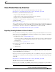
Preface Cisco Product Security Overview Cisco Product Security Overview Cisco provides a free online Security Vulnerability Policy portal at this URL: http://www.cisco.com/en/US/products/products_security_vulnerability_policy.html From this site, you will find information about how to: • Report security vulnerabilities in Cisco products. • Obtain assistance with security incidents that involve Cisco products. • Register to receive security information from Cisco.
Preface Obtaining Technical Assistance Obtaining Technical Assistance Cisco Technical Support provides 24-hour-a-day award-winning technical assistance. The Cisco Technical Support & Documentation website on Cisco.com features extensive online support resources. In addition, if you have a valid Cisco service contract, Cisco Technical Assistance Center (TAC) engineers provide telephone support. If you do not have a valid Cisco service contract, contact your reseller.
Preface Obtaining Additional Publications and Information For a complete list of Cisco TAC contacts, go to this URL: http://www.cisco.com/techsupport/contacts Definitions of Service Request Severity To ensure that all service requests are reported in a standard format, Cisco has established severity definitions. Severity 1 (S1)—An existing network is down, or there is a critical impact to your business operations. You and Cisco will commit all necessary resources around the clock to resolve the situation.
Preface Obtaining Additional Publications and Information • iQ Magazine is the quarterly publication from Cisco Systems designed to help growing companies learn how they can use technology to increase revenue, streamline their business, and expand services. The publication identifies the challenges facing these companies and the technologies to help solve them, using real-world case studies and business strategies to help readers make sound technology investment decisions.
C H A P T E R 1 Overview The Cisco CRS-1 fiber-optic cleaning kit is used to clean all multiferrule (MT) optics in a Cisco CRS-1 Carrier Routing System Multishelf System using the Cisco CRS-1 fiber-optic cleaning kit. This kit cleans all optics on the S2 module, S13 module, optical interface module (OIM), and optical array cables. The cleaning tool included in the kit advances a continuous roll of lint-free cleaning cloth across the face of the optic.
Chapter 1 Overview General Reminders and Warnings General Reminders and Warnings Review these reminders and warnings before inspecting and cleaning your fiber-optic connections. Warning Because invisible radiation may be emitted from the aperture of the port when no fiber cable is connected, avoid exposure to radiation and do not stare into open apertures. Statement 125 Warning Class 1M laser radiation when open. Do not view directly with optical instruments. Statement 281 Warning Laser radiation.
Chapter 1 Overview Fiber-Optic Connectors in a Multishelf System • High-density backplane-mounted (HBMT) connectors: the optical connectors on the back of the S2 and OIMs. These connectors provide the optical path between an S2 card and its corresponding OIM. Figure 1-1 shows the fiber-optic connections in an FCC. Figure 1-2 shows the fiber-optic connections in an LCC.
Chapter 1 Overview Fiber-Optic Connectors in a Multishelf System Figure 1-2 Fiber-Optic Connections in an LCC (Rear View of Chassis) 1 3 4 B1 2 PIDVID CLEI CLASS 1 LASER LASERPRODUKT PRODUCT PRODUIT LASER DER KLASSE 1 DE CLASSE 1 PRODUCTO LASER DE CLASE 1 A0 A1 SN CRS-16-FC/M FDA A2 138668 TUS STA 1 Line card chassis 3 S13 fabric card (FC/M) 2 Optical array cable connectors 4 S13 bulkhead array adapters Cisco CRS-1 Carrier Routing System Fiber-Optic Cleaning Guide 1-4 OL-8179-02
Chapter 1 Overview About the Cisco CRS-1 Fiber-Optic Cleaning Kit About the Cisco CRS-1 Fiber-Optic Cleaning Kit All optical connections in a multishelf system are cleaned using the Cisco CRS-1 fiber-optic cleaning kit. This kit includes a tool that advances a lint-free cloth across the optical surface to remove any contaminants. The cleaning kit also includes an adapter for each connector type. The adapter ensures that the cleaning tool is inserted at the correct angle and depth for cleaning.
Chapter 1 Overview About the Cisco CRS-1 Fiber-Optic Cleaning Kit OIM/S13 Array Adapter Figure 1-5 S2 HBMT Adapter 158207 158206 Figure 1-4 Cisco CRS-1 Carrier Routing System Fiber-Optic Cleaning Guide 1-6 OL-8179-02
Chapter 1 Overview About the Cisco CRS-1 Fiber-Optic Cleaning Kit OIM HBMT Adapter 158208 Figure 1-6 Description of the Fujikura IBC Cleaning Tool Use the Fujikura IBC cleaning tool (see Figure 1-7) to clean the ferrules of your fiber optic connectors. Note Be sure to replace the protective cap after each use of the cleaning tool.
Chapter 1 Overview About the Cisco CRS-1 Fiber-Optic Cleaning Kit Figure 1-7 Fujikura IBC Cleaning Tool and Clear Protective Cap 138657 1 2 3 1 Thumb wheel 2 Cleaning head 3 Protective cap Use the thumb wheel of the cleaning tool to advance the cleaning surface (see Figure 1-8) after cleaning each ferrule so as to ensure a clean section for the next ferrule. The cleaning tool includes an alignment edge and key to help you properly align it with the optical interface surfaces during cleaning.
Chapter 1 Overview Using the Fujikura IBC Cleaning Tool Figure 1-8 Fujikura IBC Cleaning Tool Head and Alignment Edge 1 3 138658 2 1 Cleaning head 2 Alignment edge 3 Key Using the Fujikura IBC Cleaning Tool To operate the cleaning tool, complete the following steps for each ferrule: Step 1 Attach an ESD-preventive wrist strap to your wrist and connect its leash to an ESD connection socket or a bare metal surface on the chassis.
Chapter 1 Overview Using the Fujikura IBC Cleaning Tool Step 4 To clean the surface, advance the white thumb wheel until you hear two hard clicks. This action moves a continuous roll of lint-free cleaning cloth across the surface of the fibers, removing dust and other contaminants. The cleaning tool holds enough cloth to clean well over 100 ferrules. Note The thumb wheel makes a series of soft clicks followed by a “hard click” when turned.
2 C H A P T E R Cleaning the Optical Array Cable Connectors This chapter provides instructions for cleaning the ferrules in the optical array cable connectors. These connectors are at both ends of the fiber-optic cables that connect the S13 cards in the line card chassis (LCC) to the optical interface modules (OIMs) in the fabric card chassis (FCC).
Chapter 2 Cleaning the Optical Array Cable Connectors How to Clean the Optical Array Cable Connectors How to Clean the Optical Array Cable Connectors Each optical array cable connector contains six optical ferrules. To access all ferrules, you must clean three ferrules and then rotate the adapter 180 degrees to clean the remaining three ferrules. This section describes the process to clean all ferrules in an optical array cable.
Chapter 2 Cleaning the Optical Array Cable Connectors How to Clean the Optical Array Cable Connectors Cleaning an Optical Array Cable Connector 138661 Figure 2-3 Step 4 Insert the cleaning tool into the first adapter slot. Align the key on the cleaning tool with the matching notch in the adapter slot. The cleaning tool works only when the cleaning head is properly inserted. Step 5 Advance the thumb wheel until you hear two hard clicks.
Chapter 2 Cleaning the Optical Array Cable Connectors How to Clean the Optical Array Cable Connectors Cisco CRS-1 Carrier Routing System Fiber-Optic Cleaning Guide 2-4 OL-8179-02
C H A P T E R 3 Cleaning the Bulkhead Array Connectors This chapter provides instructions for cleaning the optical array connectors located on the S13 cards in the line card chassis (LCC) to the optical interface modules (OIMs) in the fabric card chassis.
Chapter 3 Cleaning the Bulkhead Array Connectors How to Clean the Bulkhead Array Connectors How to Clean the Bulkhead Array Connectors Each bulkhead array connector contains six optical ferrules. To access all ferrules, you must clean three ferrules and then rotate the adapter 180 degrees to clean the remaining three ferrules.
Chapter 3 Cleaning the Bulkhead Array Connectors How to Clean the Bulkhead Array Connectors Figure 3-2 Cleaning the Bulkhead Array Connectors OIM 1 2 3 B1 S13 card PIDVID CLEI CLASS 1 LASER LASERPRODUKT PRODUCT PRODUIT LASER DER KLASSE 1 DE CLASSE 1 PRODUCTO LASER DE CLASE 1 A0 A1 TUS STA 1 Cleaning tool 2 OIM/S13 cleaning adapter 3 138662 SN CRS-16-FC/M FDA A2 Bulkhead array connectors Cisco CRS-1 Carrier Routing System Fiber-Optic Cleaning Guide OL-8179-02 3-3
Chapter 3 Cleaning the Bulkhead Array Connectors How to Clean the Bulkhead Array Connectors To clean the bulkhead array connectors, follow these steps: Step 1 Attach an ESD-preventive wrist strap to your wrist and connect its leash to an ESD connection socket or a bare metal surface on the chassis. Step 2 Insert the array adapter into an array connector. Verify that the connector shutters open fully when you insert the adapter (see Figure 3-3).
Chapter 3 Cleaning the Bulkhead Array Connectors How to Clean the Bulkhead Array Connectors Step 4 Advance the thumb wheel until you hear two hard clicks. This advancement ensures that enough lint-free cleaning cloth advances across the face of the fibers in the ferrule. Note The thumb wheel makes a series of soft clicks followed by a “hard click” when turned. The hard click is represented by six large notches along the edge of the thumb wheel.
Chapter 3 Cleaning the Bulkhead Array Connectors How to Clean the Bulkhead Array Connectors Cisco CRS-1 Carrier Routing System Fiber-Optic Cleaning Guide 3-6 OL-8179-02
C H A P T E R 4 Cleaning the S2 HBMT Connectors This chapter provides instructions for cleaning the high-density backplane-mounted (HBMT) connectors on the rear of the S2 cards in the fabric card chassis. This chapter presents the following topics: • Information About Cleaning the S2 HBMT Connectors • Cleaning the S2 HBMT Connectors Information About Cleaning the S2 HBMT Connectors In the fabric card chassis (FCC), the S2 and OIMs connect to each other using HBMT connectors on the back of each card.
Chapter 4 Cleaning the S2 HBMT Connectors Cleaning the S2 HBMT Connectors Cleaning the S2 HBMT Connectors Each S2 HBMT connector contains four optical ferrules. To access all ferrules, you must clean two ferrules and then rotate the adapter 180 degrees to clean the remaining two ferrules, as described in the following steps: Warning Because invisible radiation may be emitted from the aperture of the port when no fiber cable is connected, avoid exposure to radiation and do not stare into open apertures.
Chapter 4 Cleaning the S2 HBMT Connectors Cleaning the S2 HBMT Connectors Figure 4-3 Sample Cleaning Adapter, Cleaning Tool, and S2 HBMT Connector 1 2 4 138665 3 1 S2 HBMT adapter 3 Metal tabs on adapter 2 Cleaning tool 4 Plastic latches on connector Step 3 Insert the cleaning tool into the first adapter slot. Align the key on the cleaning tool with the matching notch in the adapter slot. The cleaning tool works properly only when the cleaning head is properly inserted.
Chapter 4 Cleaning the S2 HBMT Connectors Cleaning the S2 HBMT Connectors Cisco CRS-1 Carrier Routing System Fiber-Optic Cleaning Guide 4-4 OL-8179-02
C H A P T E R 5 Cleaning the OIM HBMT Connectors This chapter provides instructions for cleaning the high-density backplane-mounted (HBMT) connectors on the rear of the S2 cards in the fabric card chassis. This chapter presents the following topics: • Information About Cleaning the OIM HBMT Connectors • How to Clean the OIM HBMT Connectors Information About Cleaning the OIM HBMT Connectors This chapter describes how to clean the OIM HBMT connectors.
Chapter 5 Cleaning the OIM HBMT Connectors How to Clean the OIM HBMT Connectors How to Clean the OIM HBMT Connectors Each OIM HBMT connector contains four optical ferrules. To access all ferrules, you must clean two ferrules and then rotate the adapter 180 degrees to clean the remaining two ferrules. Warning Because invisible radiation may be emitted from the aperture of the port when no fiber cable is connected, avoid exposure to radiation and do not stare into open apertures.
Chapter 5 Cleaning the OIM HBMT Connectors How to Clean the OIM HBMT Connectors Figure 5-2 Cleaning the OIM HBMT Connectors 4 3 2 158109 1 1 Cleaning tool 3 OIM HBMT connector 2 OIM HBMT adapter 4 OIM To clean the OIM HBMT connectors, follow these steps: Step 1 Attach an ESD-preventive wrist strap to your wrist and connect its leash to an ESD connection socket or a bare metal surface on the chassis. Step 2 Insert the OIM HBMT adapter into an OIM HBMT connector.
Chapter 5 Cleaning the OIM HBMT Connectors How to Clean the OIM HBMT Connectors OIM HBMT Connector with Shutters Closed and Open 1 Step 3 2 1 Shutters closed 2 Shutters fully open 138859 Figure 5-3 Insert the cleaning tool into the first adapter slot, as shown in Figure 5-4. Align the key on the cleaning tool with the matching notch in the adapter slot. The cleaning tool works only when the cleaning head is properly inserted.
Chapter 5 Cleaning the OIM HBMT Connectors How to Clean the OIM HBMT Connectors Note The thumb wheel makes a series of soft clicks followed by a "hard click" when turned. The hard click is represented by six large notches along the edge of the thumb wheel. Always advance the thumb wheel until you hear two hard clicks. Step 5 Clean the first two ferrules and then rotate the adapter to clean the remaining two ferrules. Step 6 Repeat these steps for all OIM HBMT connectors that require cleaning.
Chapter 5 Cleaning the OIM HBMT Connectors How to Clean the OIM HBMT Connectors Cisco CRS-1 Carrier Routing System Fiber-Optic Cleaning Guide 5-6 OL-8179-02
INDEX cleaning the OIM HBMT connectors (figure) A cleaning the optical array connectors adapter 2-1 cleaning the S2 HBMT connectors (figure) OIM HBMT (figure) 1-7, 5-1 rotating 180 degrees 1-10 description of 1-7 1-6, 4-1 Fujikura IBC 1-7 S2 HBMT (figure) 2-2 Fujikura IBC head array adapter using 1-6, 3-1 1-9 1-9 cleaning tool (figure) array connectors, cleaning optical 4-2 cleaning tool adapter placement example (figure) OIM/S13 (figure) 2-1, 2-2 1-5, 1-8, 2-1, 3-4, 4-3, 5-4 co
Index Fujikura IBC cleaning tool (figure) F 1-5, 1-8 Fujikura IBC cleaning tool head (figure) fiber-optic cleaning kit, about the 1-5 fiber-optic connections in an FCC (figure) 1-3 fiber-optic connections in an LCC (figure) 1-4 fiber optics G general reminders and warnings connections in an FCC (figure) 1-3 connections in an LCC (figure) 1-4 connectors in a multishelf system inspection of 1-2 H 1-2 1-1 how to clean the optical array connectors overview of cleaning 1-9 2-2 1-1 Figur
Index R related documentation reminders, general vii 1-2 rotating the adapter 180 degrees (figure) 1-10 S S2 HBMT adapter (figure) 1-6, 4-1 S2 HBMT connector (figure) 4-3 S2 HBMT connectors cleaning 4-1, 4-2 information about cleaning 4-1 S2 HBMT connectors, cleaning (figure) sample bulkhead array connector (figure) sample OIM HBMT connector (figure) 4-2 3-4 5-4 sample optical array cable connector (figure) 2-1 W warnings description (and translations) of warnings, general vi 1-2 Cisco
Index Cisco CRS-1 Carrier Routing System 16-Slot Line Card Chassis Installation Guide IN-4 OL-8179-02