C H A P T E R 2 Installation This chapter provides information on the following topics: • Preparing for Installation • Preventing Router Damage • Mounting the Router • Installing the Router • Using the Router LEDs to Check Links • Configuring the Router Cisco 827 and SOHO 77 Routers Hardware Installation Guide 78-6854-03 2-1
Chapter 2 Installation Preparing for Installation Preparing for Installation This section provides information on safety, mounting the router, and unpacking the contents of the router box. Safety This section provides safety warnings and electrostatic and router damage information for the Cisco 827 routers and SOHO 77 routers. Warnings Before installing the router, read the following warnings: Warning Only trained and qualified personnel should be allowed to install or replace this equipment.
Chapter 2 Installation Preparing for Installation Preventing Electrostatic Discharge Damage Electrostatic discharge (ESD) is a transfer of electrostatic charge between bodies of different electrostatic potentials, such as an operator and a piece of electrical equipment. It occurs when electronic components are improperly handled, and it can damage equipment and impair electrical circuitry. Electrostatic discharge is more likely to occur with the combination of synthetic fibers and dry atmosphere.
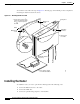
Chapter 2 Installation Preventing Router Damage To prepare for installation, follow these steps: Step 1 Obtain the ADSL line. Step 2 Remove the yellow Ethernet cable, light blue console cable, lavender ADSL cable, product documentation, and Cisco 800 Documentation CD-ROM from the Open Me First bag. Remove the desktop power supply and the black power cord from the accessory kit. Gather the Ethernet devices to be connected to the router: hub, server, workstation, or PC.
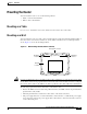
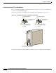
Chapter 2 Installation Mounting the Router Mounting the Router You can mount the router on one of the following surfaces: • Table or other horizontal surface • Wall or other vertical surface Mounting on a Table Do not cover or obstruct the router vents, which are located on the sides of the router. Mounting on a Wall You can mount the router on a wall or other vertical surface by using the molded mounting brackets on the bottom of the router and two number-six, 3/4-in. (M3.5 x 20 mm) screws.
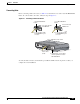
Chapter 2 Installation Installing the Router To mount the router, follow the steps in Figure 2-2. The last page of this manual provides a template for measuring the distance between the screws. Figure 2-2 Mounting Router on a Wall 1. Secure two screws 7 58 in. (19.35 cm) apart in a wall and 18 in. (0.32 cm) from the wall. 23ON 4 E 9 (1 D C D -R A XD D S T L X Mounting brackets 1 -R E X T D H E T R X N D E T Wall-mount screw 1- in. OK m) c .
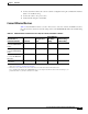
Chapter 2 Installation Installing the Router 4. Connect a terminal or PC to the router for software configuration using the command-line interface (CLI) or for troubleshooting. 5. Connect the router to the power source. 6. Verify the links using the router LEDs. Connect Ethernet Devices Table 2-2 lists the Ethernet devices you can connect to Cisco 827, Cisco 827-4V, and SOHO 77 routers; the connections for each device; and the settings of the router TO HUB/TO PC button (the default setting is IN).
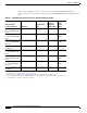
Chapter 2 Installation Installing the Router Table 2-3 lists the Ethernet devices you can connect to Cisco 827H and SOHO 77H routers, the connections for each device, and the settings of the router TO HUB/TO PC button (the default setting is IN).
Chapter 2 Installation Installing the Router Connecting Hubs Before connecting a hub to the router, see Table 2-2 to determine how to set the router TO HUB/TO PC button. To connect a hub to the router, follow the steps in Figure 2-3. Figure 2-3 Connecting a Hub to the Router 1. Set TO HUB/TO PC button. 1. Set TO HUB/TO PC button.
Chapter 2 Installation Installing the Router Connecting a Server, PC, or Workstation Before connecting a server, PC, or workstation to the router, see Table 2-2 on page 2-7 to determine how to set the router TO HUB/TO PC button. To connect a server, PC, or workstation to the router, follow the steps in Figure 2-4 on page 2-10. Figure 2-4 Connecting a Server, PC, or Workstation to the Router 1. Set TO HUB/TO PC button. 1. Set TO HUB/TO PC button.
Chapter 2 Installation Installing the Router Connect an ADSL Line The procedure for connecting an ADSL line depends on the router and, in some cases, on the location. Figure 2-5 shows how to connect the ADSL line to a cable wall jack. (Figure 2-5 depicts a Cisco 827-4V router, but the process is the same for Cisco 827, Cisco 827H, SOHO 77, and SOHO 77H routers.) Warning Do not work on the system or connect or disconnect cables during periods of lightning activity.
Chapter 2 Installation Installing the Router Connect an Analog Telephone or Fax Machine (Cisco 827-4V Routers Only) You can connect as many as four devices such as analog push button telephones or fax machines to a Cisco 827-4V router. Each device is connected to basic telephone services through the color-coded gray phone ports. To connect an analog telephone or fax machine, follow the steps in Figure 2-6. You must provide the telephone cable for connecting each device.
Chapter 2 Installation Installing the Router Table 2-4 Recommended Vendors for Master Sockets Required for United Kingdom Vendor Name Product Name For More Information RS Components Avro Pacific Telephone Ring Adapter (part number 303-2000) http://www.rswww.com/ Tandy Export Adapter (part number 2797057) http://www.tandy.co.uk/ Connect a Terminal or PC to the Router’s Console Port (Optional) You can connect either a terminal or a PC to the router’s console port.
Chapter 2 Installation Installing the Router Connect the AC Adapter To connect the power supply, follow the steps in Figure 2-8. (Figure 2-8 depicts a Cisco 827-4V router, but the process is the same for the Cisco 827, Cisco 827H, SOHO 77, and SOHO 77H routers.) Warning The device is designed to work with TN power systems. Warning This product relies on the building’s installation for short-circuit (overcurrent) protection. Ensure that a fuse or circuit breaker no larger than 120 VAC, 15A U.S.
Chapter 2 Installation Using the Router LEDs to Check Links Using the Router LEDs to Check Links Use the LEDs on the front of the router to check the links between the router and attached Ethernet devices or telephones. Use Table 2-5 to verify the link status of devices attached to Cisco 827, Cisco 827-4V, and SOHO 77 routers.
Chapter 2 Installation Configuring the Router Configuring the Router When you have finished installing the router, you must configure the router software. First, check PC configurations to ensure that all PCs will be able to communicate with the router. Then configure the router software using the web interface.
Chapter 2 Installation Configuring the Router Tip If the CRWS home page does not appear when you enter the URL http://10.10.10.1, test the connection between the PC and the router by doing the following: 1. Check that the OK LED on the router is on, and check the cable connection between the router and the PC. Be sure that the TO HUB/TO PC button is in the correct position. The button is in the correct position if the LED for the port on the front of the router is on. 2.
Chapter 2 Installation Configuring the Router Cisco 827 and SOHO 77 Routers Hardware Installation Guide 2-18 78-6854-03