
User manual

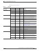


Table Of Contents
- Cisco Aironet 1130AG Series Access Point Hardware Installation Guide
- Contents
- Preface
- Overview
- Installing the Access Point
- Safety Information
- Warnings
- Unpacking the Access Point
- Basic Installation Guidelines
- Controller Discovery Process for Lightweight Access Points
- Deploying the Access Points on the Wireless Network
- Opening the Access Point Cover
- Mounting the Access Point on a Horizontal Surface
- Mounting the Access Point Below a Suspended Ceiling
- Mounting the Access Point Above a Suspended Ceiling
- Mounting Access Point on a Network Cable Box
- Mounting Access Point on a Desktop or Shelf
- Attaching the Access Point to the Mounting Plate
- Securing the Access Point
- Connecting the Ethernet and Power Cables
- Rotating the Cisco Logo
- Troubleshooting Autonomous Access Points
- Checking the Autonomous Access Point LEDs
- Checking Basic Settings
- Low Power Condition for Autonomous Access Points
- Running the Carrier Busy Test
- Running the Ping Test
- Resetting to the Default Configuration
- Reloading the Access Point Image
- Obtaining the Access Point Image File
- Connecting to the Access Point Console Port
- Obtaining the TFTP Server Software
- Troubleshooting Lightweight Access Points
- Guidelines for Using 1130AG Series Lightweight Access Points
- Checking the Lightweight Access Point LEDs
- Low Power Condition for Lightweight Access Points
- Manually Configuring Controller Information Using the Access Point CLI
- Returning the Access Point to Autonomous Mode
- Obtaining the Autonomous Access Point Image File
- Connecting to the Access Point Console Port
- Obtaining the TFTP Server Software
- Translated Safety Warnings
- Declarations of Conformity and Regulatory Information
- Manufacturers Federal Communication Commission Declaration of Conformity Statement
- VCCI Statement for Japan
- Industry Canada
- European Community, Switzerland, Norway, Iceland, and Liechtenstein
- Declaration of Conformity for RF Exposure
- Guidelines for Operating Cisco Aironet Access Points in Japan
- Administrative Rules for Cisco Aironet Access Points in Taiwan
- Declaration of Conformity Statements
- Access Point Specifications
- Channels and Maximum Power Levels
- Console Cable Pinouts
- Priming Lightweight Access Points Prior to Deployment
- Configuring DHCP Option 43 for Lightweight Access Points
- Glossary
- Index

3-7
Cisco Aironet 1130AG Series Access Point Hardware Installation Guide
OL-8369-05
Chapter 3 Troubleshooting Autonomous Access Points
Low Power Condition for Autonomous Access Points
The access point supports Intelligent Power Management and as a result of the power negotiations, the
access point will either enter full power mode or remain in low power mode with the radios disabled.
Note Independent of the power negotiations, the access point hardware also uses the 802.3af classification
scheme to indicate the power required from the power source. However, the power source cannot report
the power available to the access point unless the power source also supports Intelligent Power
Management.
Some Cisco switches that are capable of supplying sufficient power require a software upgrade to
support Intelligent Power Management. If the software upgrade is not desired, you can configure the
access point to operate in pre-standard compatibility mode and the access point automatically enters full
power mode if these Cisco switches are detected in the received CDP ID field.
When the access point determines that sufficient power is not available for full power operation, an error
message is logged and the Status LED turns amber to indicate low power mode (see the
“Checking the
Autonomous Access Point LEDs” section on page 3-2 and the “Inline Power Status Messages” section
on page 3-7).
Tip If your switch is capable of supplying sufficient power for full operation but the access point remains in
low-power mode, your access point or your switch (or both) might be misconfigured (see
Table 3-2 and
Table 3-3).
If your inline power source is not able to supply sufficient power for full operation, you should consider
these options:
• Upgrade to a higher-powered switch
• Use a Cisco Aironet power injector on the switch port
• Use the 48-VDC power module to locally power the access point
Inline Power Status Messages
These messages are logged on the console port by the access point to report the power condition:
• %CDP_PD-4-POWER_OK: Full Power - AC_ADAPTOR inline power source—This message
indicates the access point is using the power module and can support full-power operation.
• %CDP_PD-4-POWER_OK: Full Power - NEGOTIATED inline power source—This message
indicates the access point is operating at full power and has successfully negotiated for 12.95 W of
power from a Cisco switch supporting Cisco Intelligent Power Management.
• %CDP_PD-4-POWER_OK: Full Power - HIGH_POWER_CLASSIC inline power source—This
message indicates the access point is operating at full power because it has been configured for
pre-standard compatibility mode and has detected a Cisco switch that does not support Intelligent
Power Management but is able to supply sufficient power to the access point.
• %CDP_PD-4-POWER_OK: Full Power - INJECTOR_CONFIGURED_ON_SOURCE inline power
source—This message indicates the access point is operating at full power because it is connected
to a Cisco switch that supports Intelligent Power Management and the switch has been configured
with the power inline never command.
• %CDP_PD-4-POWER_OK: Full power - INJECTOR_CONFIGURED_ON_CURRENT_PORT
inline power source—This message indicates the access point is operating at full power because it
has been configured to expect a power injector on this port.