
User manual

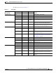


Table Of Contents
- Cisco Aironet 1130AG Series Access Point Hardware Installation Guide
- Contents
- Preface
- Overview
- Installing the Access Point
- Safety Information
- Warnings
- Unpacking the Access Point
- Basic Installation Guidelines
- Controller Discovery Process for Lightweight Access Points
- Deploying the Access Points on the Wireless Network
- Opening the Access Point Cover
- Mounting the Access Point on a Horizontal Surface
- Mounting the Access Point Below a Suspended Ceiling
- Mounting the Access Point Above a Suspended Ceiling
- Mounting Access Point on a Network Cable Box
- Mounting Access Point on a Desktop or Shelf
- Attaching the Access Point to the Mounting Plate
- Securing the Access Point
- Connecting the Ethernet and Power Cables
- Rotating the Cisco Logo
- Troubleshooting Autonomous Access Points
- Checking the Autonomous Access Point LEDs
- Checking Basic Settings
- Low Power Condition for Autonomous Access Points
- Running the Carrier Busy Test
- Running the Ping Test
- Resetting to the Default Configuration
- Reloading the Access Point Image
- Obtaining the Access Point Image File
- Connecting to the Access Point Console Port
- Obtaining the TFTP Server Software
- Troubleshooting Lightweight Access Points
- Guidelines for Using 1130AG Series Lightweight Access Points
- Checking the Lightweight Access Point LEDs
- Low Power Condition for Lightweight Access Points
- Manually Configuring Controller Information Using the Access Point CLI
- Returning the Access Point to Autonomous Mode
- Obtaining the Autonomous Access Point Image File
- Connecting to the Access Point Console Port
- Obtaining the TFTP Server Software
- Translated Safety Warnings
- Declarations of Conformity and Regulatory Information
- Manufacturers Federal Communication Commission Declaration of Conformity Statement
- VCCI Statement for Japan
- Industry Canada
- European Community, Switzerland, Norway, Iceland, and Liechtenstein
- Declaration of Conformity for RF Exposure
- Guidelines for Operating Cisco Aironet Access Points in Japan
- Administrative Rules for Cisco Aironet Access Points in Taiwan
- Declaration of Conformity Statements
- Access Point Specifications
- Channels and Maximum Power Levels
- Console Cable Pinouts
- Priming Lightweight Access Points Prior to Deployment
- Configuring DHCP Option 43 for Lightweight Access Points
- Glossary
- Index

3-4
Cisco Aironet 1130AG Series Access Point Hardware Installation Guide
OL-8369-05
Chapter 3 Troubleshooting Autonomous Access Points
Checking Basic Settings
Checking Basic Settings
Mismatched basic settings are the most common causes of lost connectivity with wireless clients. If the
access point does not communicate with client devices, check the following areas.
Default IP Address Behavior
When you connect an 1130AG access point running Cisco IOS Release 12.3(2)JA or later software with
a default configuration to your LAN, the access point requests an IP address from your DHCP server,
and if it does not receive an IP address, it continues to send requests indefinitely.
Default SSID and Radio Behavior
In Cisco IOS Relese 12.3(2)JA2 and earlier, the access point radios are enabled by default and the default
SSIDs are tsunami.
In Cisco IOS Release 12.3(4)JA and later, the access point radios are disabled by default, and there are
no default SSIDs. You must create an SSID and enable the radio before the access point will allow
wireless associations from other devices. These changes to the default configuration improve the
security of newly installed access points. Refer to the Cisco IOS Software Configuration Guide for Cisco
Aironet Access Points for instructions on configuring the SSID and the
“Enable Radio Interfaces”
section on page 3-5 for instructions on enabling the radio interfaces.
Boot loader errors Red Red Red DRAM memory test failure.
Off Red Blinking red
and blue
Flash file system failure.
Off Amber Blinking red
and
blue-green
Environment variable (ENVAR) failure.
Amber Off Blinking red
and yellow
Bad MAC address.
Red Off Blinking red
and off
Ethernet failure during image recovery.
Amber Amber Blinking red
and off
Boot environment error.
Red Amber Blinking red
and off
No Cisco IOS image file.
Amber Amber Blinking red
and off
Boot failure.
Table 3-1 LED Signals (continued)
Message type
Cable Bay Area Top of Unit
MeaningEthernet LED Radio LED Status LED