
User manual

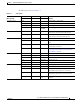


Table Of Contents
- Cisco Aironet 1130AG Series Access Point Hardware Installation Guide
- Contents
- Preface
- Overview
- Installing the Access Point
- Safety Information
- Warnings
- Unpacking the Access Point
- Basic Installation Guidelines
- Controller Discovery Process for Lightweight Access Points
- Deploying the Access Points on the Wireless Network
- Opening the Access Point Cover
- Mounting the Access Point on a Horizontal Surface
- Mounting the Access Point Below a Suspended Ceiling
- Mounting the Access Point Above a Suspended Ceiling
- Mounting Access Point on a Network Cable Box
- Mounting Access Point on a Desktop or Shelf
- Attaching the Access Point to the Mounting Plate
- Securing the Access Point
- Connecting the Ethernet and Power Cables
- Rotating the Cisco Logo
- Troubleshooting Autonomous Access Points
- Checking the Autonomous Access Point LEDs
- Checking Basic Settings
- Low Power Condition for Autonomous Access Points
- Running the Carrier Busy Test
- Running the Ping Test
- Resetting to the Default Configuration
- Reloading the Access Point Image
- Obtaining the Access Point Image File
- Connecting to the Access Point Console Port
- Obtaining the TFTP Server Software
- Troubleshooting Lightweight Access Points
- Guidelines for Using 1130AG Series Lightweight Access Points
- Checking the Lightweight Access Point LEDs
- Low Power Condition for Lightweight Access Points
- Manually Configuring Controller Information Using the Access Point CLI
- Returning the Access Point to Autonomous Mode
- Obtaining the Autonomous Access Point Image File
- Connecting to the Access Point Console Port
- Obtaining the TFTP Server Software
- Translated Safety Warnings
- Declarations of Conformity and Regulatory Information
- Manufacturers Federal Communication Commission Declaration of Conformity Statement
- VCCI Statement for Japan
- Industry Canada
- European Community, Switzerland, Norway, Iceland, and Liechtenstein
- Declaration of Conformity for RF Exposure
- Guidelines for Operating Cisco Aironet Access Points in Japan
- Administrative Rules for Cisco Aironet Access Points in Taiwan
- Declaration of Conformity Statements
- Access Point Specifications
- Channels and Maximum Power Levels
- Console Cable Pinouts
- Priming Lightweight Access Points Prior to Deployment
- Configuring DHCP Option 43 for Lightweight Access Points
- Glossary
- Index

3-3
Cisco Aironet 1130AG Series Access Point Hardware Installation Guide
OL-8369-05
Chapter 3 Troubleshooting Autonomous Access Points
Checking the Autonomous Access Point LEDs
The LED signals are listed in Table 3-1.
Ta b l e 3-1 LED Signals
Message type
Cable Bay Area Top of Unit
MeaningEthernet LED Radio LED Status LED
Operating status Green — — Ethernet link is operational.
Blinking green — — Transmitting or receiving Ethernet packets.
— Blinking green — Transmitting or receiving radio packets.
— — Blinking
dark blue
Software upgrade in progress
Association status — — Light green Normal operating condition, but no wireless
client devices are associated with the unit.
— — Blue Normal operating condition, at least one wireless
client device is associated with the unit.
Cisco IOS errors Blinking amber — — Transmit or receive Ethernet errors.
— Blinking amber — Maximum retries or buffer full occurred on the
radio.
Red Red Amber Software failure; try disconnecting and
reconnecting unit power.
— — Amber General warning, insufficient inline power (see
the
“Low Power Condition for Autonomous
Access Points” section).
Boot loader status Green Green Green DRAM memory test ok.
Off Blinking green Blue-green Initialize Flash file system.
Off Green Pink Flash memory test ok.
Green Off Dark blue Ethernet test ok.
Green Green Green Starting Cisco IOS.
Boot loader warnings Off Off Yellow Ethernet link not operational.
Red Off Yellow Ethernet failure.
Amber Off Yellow Configuration recovery in progress
(Mode button pressed for 2 to 3 seconds).
Off Red Pink Image recovery
(Mode button pressed for 20 to 30 seconds).
Blinking green Blinking red Blinking
pink
Image recovery in progress and Mode button is
released.