
User manual

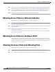


Table Of Contents
- Cisco Aironet 1130AG Series Access Point Hardware Installation Guide
- Contents
- Preface
- Overview
- Installing the Access Point
- Safety Information
- Warnings
- Unpacking the Access Point
- Basic Installation Guidelines
- Controller Discovery Process for Lightweight Access Points
- Deploying the Access Points on the Wireless Network
- Opening the Access Point Cover
- Mounting the Access Point on a Horizontal Surface
- Mounting the Access Point Below a Suspended Ceiling
- Mounting the Access Point Above a Suspended Ceiling
- Mounting Access Point on a Network Cable Box
- Mounting Access Point on a Desktop or Shelf
- Attaching the Access Point to the Mounting Plate
- Securing the Access Point
- Connecting the Ethernet and Power Cables
- Rotating the Cisco Logo
- Troubleshooting Autonomous Access Points
- Checking the Autonomous Access Point LEDs
- Checking Basic Settings
- Low Power Condition for Autonomous Access Points
- Running the Carrier Busy Test
- Running the Ping Test
- Resetting to the Default Configuration
- Reloading the Access Point Image
- Obtaining the Access Point Image File
- Connecting to the Access Point Console Port
- Obtaining the TFTP Server Software
- Troubleshooting Lightweight Access Points
- Guidelines for Using 1130AG Series Lightweight Access Points
- Checking the Lightweight Access Point LEDs
- Low Power Condition for Lightweight Access Points
- Manually Configuring Controller Information Using the Access Point CLI
- Returning the Access Point to Autonomous Mode
- Obtaining the Autonomous Access Point Image File
- Connecting to the Access Point Console Port
- Obtaining the TFTP Server Software
- Translated Safety Warnings
- Declarations of Conformity and Regulatory Information
- Manufacturers Federal Communication Commission Declaration of Conformity Statement
- VCCI Statement for Japan
- Industry Canada
- European Community, Switzerland, Norway, Iceland, and Liechtenstein
- Declaration of Conformity for RF Exposure
- Guidelines for Operating Cisco Aironet Access Points in Japan
- Administrative Rules for Cisco Aironet Access Points in Taiwan
- Declaration of Conformity Statements
- Access Point Specifications
- Channels and Maximum Power Levels
- Console Cable Pinouts
- Priming Lightweight Access Points Prior to Deployment
- Configuring DHCP Option 43 for Lightweight Access Points
- Glossary
- Index

2-19
Cisco Aironet 1130AG Series Access Point Hardware Installation Guide
OL-8369-05
Chapter 2 Installing the Access Point
Securing the Access Point
Securing the Access Point to the Mounting Plate
The mounting plate provides two methods of securing your access point to restrict its removal:
• You can use the security hasp adapter (supplied) and a padlock (that you provide) to secure your
access point to the mounting plate (refer to
Figure 1-3 on page 1-7). Compatible padlocks are Master
Lock models 120T or 121T.
Note The security hasp adapter covers the cable bay area (including the power port, Ethernet port,
console port, and the mode button) to prevent the installation or removal of the cables or the
activation of the mode button.
• You can use the 8 x 32 x 3/16 in. pan head screw (provided) or a tamper-resistant head screw (that
you provide) to attach the access point to the mounting plate using the security screw hole (see
Figure 2-10).
Note Using a tamper-resistant head screw to secure the access point to the mounting plate does
not prevent someone from inserting or removing the access point cables or pressing the
mode button.
Follow these instructions to install the security hasp adapter:
Step 1 Open the access point cover (see the “Opening the Access Point Cover” section on page 2-11).
Step 2 Carefully tilt the security hasp adapter and insert the access point security hasp tab into the notch on the
security hasp adapter (see
Figure 2-12).
Figure 2-12 Installing the Security Hasp Adapter
Step 3 Push down on the security hasp adapter to expose the padlock post hole.
1 Access point security hasp tab 3 Security hasp adapter
2 Security hasp notch
2
3
1
121780