
User manual


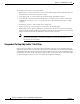


Table Of Contents
- Cisco Aironet 1130AG Series Access Point Hardware Installation Guide
- Contents
- Preface
- Overview
- Installing the Access Point
- Safety Information
- Warnings
- Unpacking the Access Point
- Basic Installation Guidelines
- Controller Discovery Process for Lightweight Access Points
- Deploying the Access Points on the Wireless Network
- Opening the Access Point Cover
- Mounting the Access Point on a Horizontal Surface
- Mounting the Access Point Below a Suspended Ceiling
- Mounting the Access Point Above a Suspended Ceiling
- Mounting Access Point on a Network Cable Box
- Mounting Access Point on a Desktop or Shelf
- Attaching the Access Point to the Mounting Plate
- Securing the Access Point
- Connecting the Ethernet and Power Cables
- Rotating the Cisco Logo
- Troubleshooting Autonomous Access Points
- Checking the Autonomous Access Point LEDs
- Checking Basic Settings
- Low Power Condition for Autonomous Access Points
- Running the Carrier Busy Test
- Running the Ping Test
- Resetting to the Default Configuration
- Reloading the Access Point Image
- Obtaining the Access Point Image File
- Connecting to the Access Point Console Port
- Obtaining the TFTP Server Software
- Troubleshooting Lightweight Access Points
- Guidelines for Using 1130AG Series Lightweight Access Points
- Checking the Lightweight Access Point LEDs
- Low Power Condition for Lightweight Access Points
- Manually Configuring Controller Information Using the Access Point CLI
- Returning the Access Point to Autonomous Mode
- Obtaining the Autonomous Access Point Image File
- Connecting to the Access Point Console Port
- Obtaining the TFTP Server Software
- Translated Safety Warnings
- Declarations of Conformity and Regulatory Information
- Manufacturers Federal Communication Commission Declaration of Conformity Statement
- VCCI Statement for Japan
- Industry Canada
- European Community, Switzerland, Norway, Iceland, and Liechtenstein
- Declaration of Conformity for RF Exposure
- Guidelines for Operating Cisco Aironet Access Points in Japan
- Administrative Rules for Cisco Aironet Access Points in Taiwan
- Declaration of Conformity Statements
- Access Point Specifications
- Channels and Maximum Power Levels
- Console Cable Pinouts
- Priming Lightweight Access Points Prior to Deployment
- Configuring DHCP Option 43 for Lightweight Access Points
- Glossary
- Index
2-9
Cisco Aironet 1130AG Series Access Point Hardware Installation Guide
OL-8369-05
Chapter 2 Installing the Access Point
Deploying the Access Points on the Wireless Network
Figure 2-3 T-Rail Clip Features
The adjustable T-rail clip attaches to the mounting plate using four 6 x 32 x 1/4 inch flat head screws.
The A, B, and C holes on the T-rail clips and the mounting plate correspond to these T-rail widths:
• A holes—used for 1 1/2 in (38 mm) T-rails
• B holes—used for 15/16 in (24 mm) T-rails
• C holes—used for 9/16 in (15 mm) T-rails
1 T-rail locking screws 3 T-rail width adjustment detents (A, B, C)
correspond to the A, B, and C holes on the
mounting plate
2 Mounting plate screw holes
(8 x 32 flat head screw)
121758
3
3
1
1
2
2
2
2
CEILING
GRID
WIDTH
38 24 15
ABC
1-1/2 15/16 9/16
MM
INCH
CEILING
GRID
WIDTH
38 24 15
ABC
1-1/2 15/16 9/16
MM
INCH