
User manual


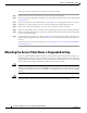
Table Of Contents
- Cisco Aironet 1130AG Series Access Point Hardware Installation Guide
- Contents
- Preface
- Overview
- Installing the Access Point
- Safety Information
- Warnings
- Unpacking the Access Point
- Basic Installation Guidelines
- Controller Discovery Process for Lightweight Access Points
- Deploying the Access Points on the Wireless Network
- Opening the Access Point Cover
- Mounting the Access Point on a Horizontal Surface
- Mounting the Access Point Below a Suspended Ceiling
- Mounting the Access Point Above a Suspended Ceiling
- Mounting Access Point on a Network Cable Box
- Mounting Access Point on a Desktop or Shelf
- Attaching the Access Point to the Mounting Plate
- Securing the Access Point
- Connecting the Ethernet and Power Cables
- Rotating the Cisco Logo
- Troubleshooting Autonomous Access Points
- Checking the Autonomous Access Point LEDs
- Checking Basic Settings
- Low Power Condition for Autonomous Access Points
- Running the Carrier Busy Test
- Running the Ping Test
- Resetting to the Default Configuration
- Reloading the Access Point Image
- Obtaining the Access Point Image File
- Connecting to the Access Point Console Port
- Obtaining the TFTP Server Software
- Troubleshooting Lightweight Access Points
- Guidelines for Using 1130AG Series Lightweight Access Points
- Checking the Lightweight Access Point LEDs
- Low Power Condition for Lightweight Access Points
- Manually Configuring Controller Information Using the Access Point CLI
- Returning the Access Point to Autonomous Mode
- Obtaining the Autonomous Access Point Image File
- Connecting to the Access Point Console Port
- Obtaining the TFTP Server Software
- Translated Safety Warnings
- Declarations of Conformity and Regulatory Information
- Manufacturers Federal Communication Commission Declaration of Conformity Statement
- VCCI Statement for Japan
- Industry Canada
- European Community, Switzerland, Norway, Iceland, and Liechtenstein
- Declaration of Conformity for RF Exposure
- Guidelines for Operating Cisco Aironet Access Points in Japan
- Administrative Rules for Cisco Aironet Access Points in Taiwan
- Declaration of Conformity Statements
- Access Point Specifications
- Channels and Maximum Power Levels
- Console Cable Pinouts
- Priming Lightweight Access Points Prior to Deployment
- Configuring DHCP Option 43 for Lightweight Access Points
- Glossary
- Index

2-8
Cisco Aironet 1130AG Series Access Point Hardware Installation Guide
OL-8369-05
Chapter 2 Installing the Access Point
Deploying the Access Points on the Wireless Network
The mounting plate features are described below:
• Keyhole clips—used to attach the access point to the mounting plate. The keyhole clips slide into
the keyhole slots on the bottom of the access point.
• Screw holes (A, B, C)—used to attach the suspended ceiling adjustable T-rail clips.
• Screw hole (X)—used to attach the mounting plate to a network cable box, wall, or ceiling. The
mounting kit contains two 8 x 32 x 1 inch pan head screws and wall anchors for wall or ceiling
mounting.
• T-bar hanger clip hole—used to attach a T-bar hanger clip.
• Security screw hole—used to secure the access point to the mounting plate.
• Padlock hole—used to attach a padlock (user provided) to secure the access point to the mounting
plate. Compatible padlocks are Master Lock models 120T and 121T or equivalent. The security hasp
adapter can also be used with the padlock for increase security protection.
Note The security hasp covers the cable bay area ( including the power port, Ethernet port, console
port, and the mode button) to prevent the installation or removal of the cables or the
activation of the mode button.
Suspended Ceiling Adjustable T-Rail Clips
The accessory kit contains two suspended ceiling adjustable T-rail clips; one for standard ceiling tile
rails and the other for recessed ceiling tile rails. The clips are adjustable to accomodate three standard
T-rail widths. Each clip contains detents that are used to adjust the clip to the T-rail. Each detent contains
markings that indicate the T-rail width and the hole letter that corresponds to the correct mounting holes
on the mounting plate.
Figure 2-3 shows the details of the adjustable T-rail clips.