
User manual
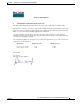


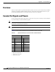
Table Of Contents
- Cisco Aironet 1130AG Series Access Point Hardware Installation Guide
- Contents
- Preface
- Overview
- Installing the Access Point
- Safety Information
- Warnings
- Unpacking the Access Point
- Basic Installation Guidelines
- Controller Discovery Process for Lightweight Access Points
- Deploying the Access Points on the Wireless Network
- Opening the Access Point Cover
- Mounting the Access Point on a Horizontal Surface
- Mounting the Access Point Below a Suspended Ceiling
- Mounting the Access Point Above a Suspended Ceiling
- Mounting Access Point on a Network Cable Box
- Mounting Access Point on a Desktop or Shelf
- Attaching the Access Point to the Mounting Plate
- Securing the Access Point
- Connecting the Ethernet and Power Cables
- Rotating the Cisco Logo
- Troubleshooting Autonomous Access Points
- Checking the Autonomous Access Point LEDs
- Checking Basic Settings
- Low Power Condition for Autonomous Access Points
- Running the Carrier Busy Test
- Running the Ping Test
- Resetting to the Default Configuration
- Reloading the Access Point Image
- Obtaining the Access Point Image File
- Connecting to the Access Point Console Port
- Obtaining the TFTP Server Software
- Troubleshooting Lightweight Access Points
- Guidelines for Using 1130AG Series Lightweight Access Points
- Checking the Lightweight Access Point LEDs
- Low Power Condition for Lightweight Access Points
- Manually Configuring Controller Information Using the Access Point CLI
- Returning the Access Point to Autonomous Mode
- Obtaining the Autonomous Access Point Image File
- Connecting to the Access Point Console Port
- Obtaining the TFTP Server Software
- Translated Safety Warnings
- Declarations of Conformity and Regulatory Information
- Manufacturers Federal Communication Commission Declaration of Conformity Statement
- VCCI Statement for Japan
- Industry Canada
- European Community, Switzerland, Norway, Iceland, and Liechtenstein
- Declaration of Conformity for RF Exposure
- Guidelines for Operating Cisco Aironet Access Points in Japan
- Administrative Rules for Cisco Aironet Access Points in Taiwan
- Declaration of Conformity Statements
- Access Point Specifications
- Channels and Maximum Power Levels
- Console Cable Pinouts
- Priming Lightweight Access Points Prior to Deployment
- Configuring DHCP Option 43 for Lightweight Access Points
- Glossary
- Index

E-2
Cisco Aironet 1130AG Series Access Point Hardware Installation Guide
OL-8369-05
Appendix E Console Cable Pinouts
Overview
Overview
The access point requires a special serial cable that connects the access point serial console port (RJ-45
connector) to your PC’s COM port (DB-9 connector). This cable can be purchased from Cisco (part
number AIR-CONCAB1200) or can be built using the pinouts in this appendix.
Console Port Signals and Pinouts
Use the console RJ-45 to DB-9 serial cable to connect the access point’s console port to the COM port
of your PC running a terminal emulation program.
Note Both the Ethernet and console ports use RJ-45 connectors. Be careful to avoid accidently connecting the
serial cable to the Ethernet port connector.
Note After completing your configuration changes, you must remove the serial console cable from the access
point.
Table E-1 lists the signals and pinouts for the console RJ-45 to DB-9 serial cable.
Ta b l e E-1 Signals and Pinouts for a Console RJ-45 to DB-9 Serial Cable
Console Port PC COM Port
RJ-45 DB-9
Pins Signals Pins Signals
1 NC
1
1. NC indicates not connected.
– –
2 NC
1
– –
3 TXD
2
2. TXD indicates transmit data.
2 RXD
3
3. RXD indicates receive data.
4 GND
4
4. GND indicates ground.
5 GND
4
5 GND
3
5 GND
4
6 RXD
5
3 TXD
2
7 NC
1
– –
8 NC
1
– –