Cisco CompactFlash Adapter for Bootflash Upgrade Installation Note Product Numbers: WS-CF-UPG=, CF-ADAPTER= This publication describes how to replace the switch processor (SP) bootflash memory module (DIMM) with CompactFlash on the Supervisor Engine 720.
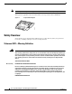
Safety Overview Note The CompactFlash adapter is not supported in systems that run the Catalyst operating system. This upgrade is applicable only for the SP bootflash; it is independent from the SP DRAM. Figure 1 CompactFlash Adapter 144401 Cisco Sy stems Safety Overview Safety warnings appear throughout this publication in procedures that may harm you if performed incorrectly. A warning symbol precedes each warning statement.
Safety Overview Varoitus TÄRKEITÄ TURVALLISUUSOHJEITA Tämä varoitusmerkki merkitsee vaaraa. Tilanne voi aiheuttaa ruumiillisia vammoja. Ennen kuin käsittelet laitteistoa, huomioi sähköpiirien käsittelemiseen liittyvät riskit ja tutustu onnettomuuksien yleisiin ehkäisytapoihin. Turvallisuusvaroitusten käännökset löytyvät laitteen mukana toimitettujen käännettyjen turvallisuusvaroitusten joukosta varoitusten lopussa näkyvien lausuntonumeroiden avulla.
Safety Overview Aviso INSTRUÇÕES IMPORTANTES DE SEGURANÇA Este símbolo de aviso significa perigo. Você está em uma situação que poderá ser causadora de lesões corporais. Antes de iniciar a utilização de qualquer equipamento, tenha conhecimento dos perigos envolvidos no manuseio de circuitos elétricos e familiarize-se com as práticas habituais de prevenção de acidentes.
Safety Overview Aviso INSTRUÇÕES IMPORTANTES DE SEGURANÇA Este símbolo de aviso significa perigo. Você se encontra em uma situação em que há risco de lesões corporais. Antes de trabalhar com qualquer equipamento, esteja ciente dos riscos que envolvem os circuitos elétricos e familiarize-se com as práticas padrão de prevenção de acidentes. Use o número da declaração fornecido ao final de cada aviso para localizar sua tradução nos avisos de segurança traduzidos que acompanham o dispositivo.
Safety Overview Cisco CompactFlash Adapter for Bootflash Upgrade Installation Note 6 78-17277-04
Safety Overview Cisco CompactFlash Adapter for Bootflash Upgrade Installation Note 78-17277-04 7
Installing the SP Bootflash Memory Upgrade Kit Installing the SP Bootflash Memory Upgrade Kit The SP memory upgrade procedure is divided into the following tasks: • Verifying the SP ROMMON Version, page 8 • Upgrading and Verifying the SP ROMMON Image, page 8 • Removing the Supervisor Engine 720, page 10 • Installing the CompactFlash Adapter, page 13 • Reinstalling the Supervisor Engine 720, page 16 Verifying the SP ROMMON Version An SP ROMMON upgrade may be required to support the CompactFlash ad
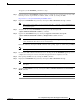
Installing the SP Bootflash Memory Upgrade Kit To upgrade your SP ROMMON, perform these steps: Step 1 Download the latest SP ROMMON (c6ksup3-rm2.srec.8.4.2) from cisco.com and copy it to any of the following locations: sup-bootflash:, bootflash:, disk0:, or disk1: by entering this URL: http://www.ciso.com/cgi-bin/tablebuild.
Installing the SP Bootflash Memory Upgrade Kit Removing the Supervisor Engine 720 Warning Only trained and qualified personnel should be allowed to install, replace, or service this equipment.
Installing the SP Bootflash Memory Upgrade Kit Step 6 Depending on the orientation of the slots in the chassis (horizontal or vertical), perform one of the following two sets of steps: Horizontal slots a. Place your thumbs on the left and right ejector levers, and simultaneously rotate the levers outward to unseat the supervisor engine from the backplane connector. (See Figure 2.) b. Grasp the front edge of the supervisor engine, and slide the supervisor engine partially out of the slot.
Installing the SP Bootflash Memory Upgrade Kit Figure 2 Opening the Ejector Levers (Horizontal Chassis Shown) 1 2 WS-X6624-FXS 3 US AT ST 24 PORT FXS ANALOG 1 4 7 10 13 16 19 22 2 5 8 11 14 17 20 23 3 6 9 12 15 18 21 24 24 -1 STATION WS-X6624-FXS 4 US AT ST 24 PORT FXS ANALOG 1 4 7 10 13 16 19 22 2 5 8 11 14 17 20 23 3 6 9 12 15 18 21 24 24 -1 STATION 5 1 WS-X6348-RJ-45V 2 12 14 24 26 36 6 38 48 2 3 4 5 6 7 8 9 10 11 12 13
Installing the SP Bootflash Memory Upgrade Kit Figure 3 Removing the Module from the Chassis (Horizontal Chassis Shown) 1 2 WS-X6624-FXS 3 US AT ST 24 PORT FXS ANALOG 1 4 7 10 13 16 19 22 2 5 8 11 14 17 20 23 3 6 9 12 15 18 21 24 7 10 13 16 19 22 24 -1 STATION WS-X6624-FXS 4 US AT ST 24 PORT FXS ANALOG 1 4 2 5 8 11 14 17 20 23 3 6 9 12 15 18 21 24 24 -1 STATION 5 WS-X6348-RJ-45V 1 2 12 14 24 6 26 36 38 48 2 3 4 5 6 7 8 9 10
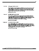
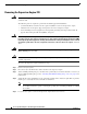
Installing the SP Bootflash Memory Upgrade Kit Figure 4 SP and RP DIMM Locations on the Supervisor Engine 720 RP Bootflash 144402 SP Bootflash Step 2 Release the SP DIMM from the socket by simultaneously releasing the two locking spring clip tabs on either side of the DIMM socket. (See Figure 5, left view.) The DIMM will flip up in the socket. (See Figure 5, right view.) Step 3 Hold the DIMM by its edges and carefully remove it from the DIMM socket.
Installing the SP Bootflash Memory Upgrade Kit Step 5 Open the antistatic bag containing the SP CompactFlash adapter. Note Step 6 Carefully align the CompactFlash adapter edge connector with the DIMM socket. Slide the CompactFlash adapter edge connector at an angle into the socket. (See Figure 6.) Note Step 7 The SP CompactFlash adapter has a label attached to the CompactFlash identifying it as the SP CompactFlash adapter.
Installing the SP Bootflash Memory Upgrade Kit Reinstalling the Supervisor Engine 720 Caution During this procedure, wear grounding wrist straps and handle modules by the carrier edges only to avoid ESD damage to the card. To reinstall the Supervisor Engine 720 in the chassis, follow these steps: Step 1 Attach an ESD grounding strap to your wrist and to ground.
Installing the SP Bootflash Memory Upgrade Kit Figure 7 Positioning the Module in a Horizontal Slot Chassis Insert module between slot guides EMI gasket 3 4 5 6 4 5 6 1 2 3 4 FAN STATUS 5 EMI gasket 91527 6 o o INPUT OK FAN OK OUTPUT FAIL INPUT OK FAN OK OUTPUT FAIL WS-SUP72 SUPERVISOR 720 WITH INTEGRATED SWITCH FABRIC Ejector lever fully extended Cisco CompactFlash Adapter for Bootflash Upgrade Installation Note 78-17277-04 17
Installing the SP Bootflash Memory Upgrade Kit Step 4 Depending on the orientation of the slots in the chassis (horizontal or vertical), perform one of the following two sets of steps: Horizontal slots a. Position the supervisor engine in the slot. (See Figure 7.) Make sure that you align the sides of the module carrier with the slot guides on each side of the slot. b.
Installing the SP Bootflash Memory Upgrade Kit Figure 8 Clearing the EMI Gasket in a Horizontal Slot Chassis 1 2 3 Press down 4 Press down 1 2 FAN STATUS 5 6 3 5 6 4 5 6 1mm Gap between the module EMI gasket and the module above it 91528 4 Cisco CompactFlash Adapter for Bootflash Upgrade Installation Note 78-17277-04 19
Installing the SP Bootflash Memory Upgrade Kit Vertical slots a. Position the supervisor engine in the slot. (See Figure 9.) Make sure that you align the sides of the module carrier with the slot guides on the top and bottom of the slot. b. Carefully slide the supervisor engine into the slot until the EMI gasket along the right edge of the module makes contact with the module in the slot adjacent to it and both ejector levers have closed to approximately 45 degrees with respect to the module faceplate.
Installing the SP Bootflash Memory Upgrade Kit Figure 10 Clearing the EMI Gasket in a Vertical Slot Chassis Gap between the module EMI gasket and the module above it 1mm WS-SUP72 SUPERVISOR 720 WITH INTEGRATED SWITCH FABRIC. FAN STATUS 48 Press left Press left 91530 48 o o INPUT OK FAN OK OUTPUT FAIL INPUT OK c. OUTPUT FAIL Using the thumb and forefinger of each hand, grasp the two ejector levers and exert a slight pressure to the left, deflecting it approximately 0.
Removing and Installing the CompactFlash in the CompactFlash Adapter e. Tighten the two captive installation screws on the supervisor engine. Note f. Power up your system. Note g. Make sure that the ejector levers are fully closed before tightening the captive installation screws. Depending on how your system bootstring is configured, your system might stay in ROMMON. To boot the system from the CF adapter, enter the boot bootdisk: command.
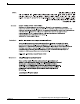
Removing and Installing the CompactFlash in the CompactFlash Adapter Figure 11 Removing the CompactFlash from the Adapter 1 2 3 Cisco Sy stems Cisco Sy stems 144747 Cisco Sy stems To install the CompactFlash in the adapter, follow these steps: Step 1 Remove the replacement CompactFlash from its packaging. Step 2 Grasp the empty adapter and the CompactFlash, and position the CompactFlash in front of the adapter as shown in Figure 12, View 1.
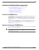
Attaching Your ESD Grounding Strap Figure 12 Installing a CompactFlash in the Adapter 1 2 3 Cisco Sy stems Cisco Sy stems 144749 Cisco Sy stems Attaching Your ESD Grounding Strap Electrostatic discharge (ESD) damage, which can occur when modules or other FRUs are improperly handled, results in intermittent or complete failures. Modules consist of printed circuit boards that are fixed in metal carriers.
Attaching Your ESD Grounding Strap Note You do not need to attach a supplemental system ground wire to the system ground lug; the lug provides a direct path to the bare metal of the chassis. After you install the system ground lug, you can perform the procedure in this section. To attach the ESD wrist strap, follow these steps: Step 1 Attach the ESD wrist strap to bare skin as follows: a.
Module Handling Guidelines Figure 13 Attaching the ESD Wrist Strap Clip to the System Ground Lug Screw Clip ESD ground strap Grounding lug Screw Side view of grounding lug Slide clip behind screw Clip installed behind screw System ground connector WS-X6K-SUP2-2GE T M LE G US O EM M T AT ST NS R SE ST SY CO PW RE Switch 100% CONSOLE PORT MODE CONSOLE SUPERVISOR2 Load PORT 1 PCMCIA PORT 2 EJECT OSM-4OC12 POS-SI NK LI 1 ST AT 3 AC TIV RX 4 PORT OC-12 POS TX TX 2 RE 4 SM IR LIN
Safety Warning Translations Safety Warning Translations This section repeats in multiple languages the basic warnings that appear in this publication. Statement 1030—Equipment Installation Warning Waarschuwing Varoitus Only trained and qualified personnel should be allowed to install, replace, or service this equipment. Deze apparatuur mag alleen worden geïnstalleerd, vervangen of hersteld door bevoegd geschoold personeel.
Safety Warning Translations Aviso Advarsel Somente uma equipe treinada e qualificada tem permissão para instalar, substituir ou dar manutenção a este equipamento. Kun uddannede personer må installere, udskifte komponenter i eller servicere dette udstyr.
Safety Warning Translations Statement 1029—Blank Faceplates and Cover Panels Warning Blank faceplates and cover panels serve three important functions: they prevent exposure to hazardous voltages and currents inside the chassis; they contain electromagnetic interference (EMI) that might disrupt other equipment; and they direct the flow of cooling air through the chassis. Do not operate the system unless all cards, faceplates, front covers, and rear covers are in place.
Safety Warning Translations ¡Advertencia! Las placas frontales y los paneles de relleno cumplen tres funciones importantes: evitan la exposición a niveles peligrosos de voltaje y corriente dentro del chasis; reducen la interferencia electromagnética (EMI) que podría perturbar la operación de otros equipos y dirigen el flujo de aire de enfriamiento a través del chasis. No haga funcionar el sistema a menos que todas las tarjetas, placas frontales, cubiertas frontales y cubiertas traseras estén en su lugar.
Safety Warning Translations Cisco CompactFlash Adapter for Bootflash Upgrade Installation Note 78-17277-04 31
Safety Warning Translations Statement 1034—Backplane Voltage Warning Waarschuwing Varoitus Hazardous voltage or energy is present on the backplane when the system is operating. Use caution when servicing. Er is gevaarlijke spanning of energie aanwezig op de achterplaat wanneer het systeem bediend wordt. Wees voorzichtig bij het onderhoud. Kun laite on toiminnassa, taustalevyyn muodostuu vaarallista jännitettä. Ole varovainen huoltaessasi laitetta.
Obtaining Documentation Advarsel Der er farlig spænding og energi på bagpladen når systemet er i brug. Vær forsigtig under servicering. Obtaining Documentation Cisco documentation and additional literature are available on Cisco.com. This section explains the product documentation resources that Cisco offers. Cisco.com You can access the most current Cisco documentation at this URL: http://www.cisco.com/techsupport You can access the Cisco website at this URL: http://www.cisco.
Documentation Feedback Product Documentation DVD The Product Documentation DVD is a library of technical product documentation on a portable medium. The DVD enables you to access installation, configuration, and command guides for Cisco hardware and software products. With the DVD, you have access to the HTML documentation and some of the PDF files found on the Cisco website at this URL: http://www.cisco.com/univercd/home/home.
Product Alerts and Field Notices Reporting Security Problems in Cisco Products Cisco is committed to delivering secure products. We test our products internally before we release them, and we strive to correct all vulnerabilities quickly. If you think that you have identified a vulnerability in a Cisco product, contact PSIRT: • For emergencies only — security-alert@cisco.
Obtaining Technical Assistance Obtaining Technical Assistance Cisco Technical Support provides 24-hour-a-day award-winning technical assistance. The Cisco Technical Support & Documentation website on Cisco.com features extensive online support resources. In addition, if you have a valid Cisco service contract, Cisco Technical Assistance Center (TAC) engineers provide telephone support. If you do not have a valid Cisco service contract, contact your reseller.
Obtaining Technical Assistance Submitting a Service Request Using the online TAC Service Request Tool is the fastest way to open S3 and S4 service requests. (S3 and S4 service requests are those in which your network is minimally impaired or for which you require product information.) After you describe your situation, the TAC Service Request Tool provides recommended solutions. If your issue is not resolved using the recommended resources, your service request is assigned to a Cisco engineer.
Obtaining Additional Publications and Information Obtaining Additional Publications and Information Information about Cisco products, technologies, and network solutions is available from various online and printed sources. • The Cisco Product Quick Reference Guide is a handy, compact reference tool that includes brief product overviews, key features, sample part numbers, and abbreviated technical specifications for many Cisco products that are sold through channel partners.
Obtaining Additional Publications and Information • “What’s New in Cisco Documentation” is an online publication that provides information about the latest documentation releases for Cisco products. Updated monthly, this online publication is organized by product category to direct you quickly to the documentation for your products. You can view the latest release of “What’s New in Cisco Documentation” at this URL: http://www.cisco.com/univercd/cc/td/doc/abtunicd/136957.
Obtaining Additional Publications and Information This document is to be used in conjunction with the Cisco IOS Software Configuration Guide. CCVP, the Cisco Logo, and the Cisco Square Bridge logo are trademarks of Cisco Systems, Inc.; Changing the Way We Work, Live, Play, and Learn is a service mark of Cisco Systems, Inc.