
Router Quick Start Guide

11
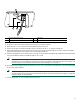
Chassis Ground Connection Installation
Note The grounding lug and Phillips-head screws are not available from Cisco Systems. Get the grounding lug from an
electrical-connector vendor and the screws from a hardware vendor. See Page 4 for the parts needed.
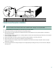
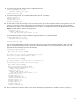
1. Locate the chassis ground connector (1) on the rear of your router chassis.
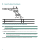
2. Insert the two screws (3) through the holes in the grounding lug (2).
3. Ensure that the grounding lug does not interfere with other router hardware, such as power supplies or the network
processing engine (NPE).
4. Use the Number 2 Phillips screwdriver to carefully tighten the screws until the grounding lug is held firmly to the chassis.
Do not overtighten the screws.
5. Use the wire stripper to strip one end of the 6-AWG wire approximately 0.75 inches (19.05 mm).
6. Insert the 6-AWG wire (4) into the wire receptacle on the grounding lug.
7. Use the crimping tool to carefully crimp the wire receptacle around the wire; this step is required to ensure a proper
mechanical connection.
8. Connect the opposite end of the grounding wire to the appropriate grounding point at your site to ensure an adequate
chassis ground.
1
Chassis ground connector
3
Screws
2
Grounding lug
4
Wire
57006
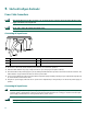
NETWORK PROCESSING ENGINE-300
1
2
3
4