Cisco 7206 Router Quick Start Guide 1 Documentation and Resources 2 Prepare for Installation 3 Rack-Mount the Router 4 Connect the Router to the Network 5 Start and Configure the Router 6 After Installation 7 Technical Assistance
1 Documentation and Resources This section contains information to help you prepare for installing the Cisco 7206 router. I contains a list of online documentation and resources. Document Revision History The Document Revision History below, records technical changes to this document. Table 1 Document Revision History Document Version Date Notes 78-12771-04 March, 2006 Adding documentation survey information. Documentation Survey Is Cisco documentation helpful? Click here or go to http://forums.
Port Adapter Documentation • Cisco 7200 Series Port Adapter Hardware Configuration Guidelines—DOC-783471= (This document provides bandwidth point information for Cisco 7200 series routers and port adapters.) http://www.cisco.com/univercd/cc/td/doc/product/core/7206/port_adp/config/index.htm • Port adapter documentation—See the document that ships with the port adapter for the customer order number. Port adapter documentation is online at: http://www.cisco.
Ordering Documentation Cisco documentation is available in the following ways: • Registered Cisco.com users (Cisco direct customers) can order Cisco product documentation from the Networking Products MarketPlace: http://www.cisco.com/cgi-bin/order/order_root.pl • Registered Cisco.com users can order the Documentation CD-ROM through the online Subscription Store: http://www.cisco.com/go/subscription • Nonregistered Cisco.
2 Prepare for Installation Warning Only trained and qualified personnel should install, replace, or service this equipment. Warning Read the installation instructions before you connect the system to its power source. Warning This unit is intended for installation in restricted access areas.
• Port adapter documentation for configuring the interfaces • T1 channel service unit/data service unit (CSU/DSU) that converts the High-Level Data Link Control (HDLC) synchronous serial data stream into a T1 data stream with the correct framing and ones density to connect a serial port to a T1 network. (Some telephone systems require a minimum number of 1 bits per time unit in a data stream, called ones density.) Several T1 CSU/DSU devices are available as additional equipment, and most provide a V.
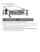
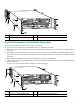
3 Rack-Mount the Router EN 5 6 3 2 1 4/1 0 AB IN-R LE D 6 Mb ING ps TOKEN RING 4 NK RJ4 5 LI MII 0 2 TX RX 4 TX 3 RX TX RX 2 RX 1 ET W ER R ES PO K O 1O C PU EN FE AB L FE E LIN K 0 FE M II T SL O 0 T C T EJE SL O PC M C IA LE D EN AB 1 53498 3 FAST ETHERNET INPUT/OUTPUT CONTROLLER 1 Cisco 7200 Series TX EN TX 1 0 CD LB ETHERNET-10BFL RX RC RD TC TD CD LB RC RD TC TD CD LB RC RD TC TD CD LB EN RC RD TC EN AB LE K 3 3 2 LI
6 3 2 1 0 EN AB LE D IN-R 4/1 6 Mb ING ps TOKEN RING 5 5 4 RJ4 LI MII 0 EN 2 TX RX 4 TX 3 RX TX M II R ES ET PO O WE K R 1O C PU EN FE AB L FE E LIN K 0 SL O T EJE C T PC M C IA EN AB LE D 0 FE SL O T RX 2 RX 1 FAST ETHERNET INPUT/OUTPUT CONTROLLER 1 Cisco 7200 Series TX EN TX 1 0 CD LB RC RD TC TD CD LB RC RD TC TD ETHERNET-10BFL RX 3 2 CD LB RC RD TC TD CD LB RC RD TC TD LE D AB K 3 LIN 1 0 2 1 FAST SERIAL EN EN 3 EN AB LE
EN 6 3 2 1 0 AB LE D IN-R 4/1 6 Mb ING ps TOKEN RING 5 FAST ETHERNET NK 4 RJ4 LI 2 4 3 2 TX RX TX RX TX TX RX 1 0 1 FAST ETHERNET INPUT/OUTPUT CONTROLLER ES ET R PO W K ER PU O C 1O EN FE AB L FE E LIN K 0 T T SL O EN PC M C EJ EC IA AB LE D 0 FE SL O M II T 1 Cisco 7200 Series RX EN TX RX CD LB RC RD TC TD CD LB RC RD TC TD CD LB RC RD TC CD LB TD EN RC RD TC TD MII 0 EN ETHERNET-10BFL FAST SERIAL 1 5 D LE AB K 3 3 2
Brackets Rear-Mounted—Front Recessed in the Rack 1. Locate the threaded screw holes in the rear sides of the chassis. 2. Align the first rack-mount bracket (1) to the threaded holes in the right side of the chassis. 3. Using a Number 2 Phillips screwdriver and two M4 x 8-mm Phillips flathead screws (2), attach the rack-mount bracket to the router. 4. Repeat Steps 2 and 3 for the bracket on the other side of the router.
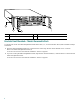
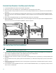
1 3 57006 2 4 NETWORK PROCESSING ENGINE-300 1 Chassis ground connector 3 Screws 2 Grounding lug 4 Wire Chassis Ground Connection Installation Note The grounding lug and Phillips-head screws are not available from Cisco Systems. Get the grounding lug from an electrical-connector vendor and the screws from a hardware vendor. See Page 4 for the parts needed. 1. Locate the chassis ground connector (1) on the rear of your router chassis. 2.
4 Connect the Router to the Network 2 ET FAST ETHERNET INPUT/OUTPUT CONTROLLER ES II 45 57007 C 1O O PW K R R L J4 IN 5 K M E II N R E J4 N 5 T 0 EC O T EJ SL PC M C IA EN AB LE D R J- PU R M FE SL O T 1 1 4 3 1 Auxiliary port-DTE-mode; EIA/TIA-232, DTE-DB-25 connector (for modem, CSU/DSU, etc.
Product Number Description C7200-I/O-2FE/E 2 autosensing Ethernet/Fast Ethernet ports; equipped with 2 RJ-45 receptacles for 10/100-Mbps operation. Note C7200-I/O-FE1 This I/O controller works only with an NPE-225, board label 72-3453 rev. A0 or higher, or faceplate label 800-05418-03 rev. A0 or higher. To check for the correct NPE-225 version in software, use the show 7200 command and look under CPU EEPROM, for Hardware Revision 1.3 or higher.
5 Start and Configure the Router Power Cable Connections Warning This unit might have more than one power cord. To reduce the risk of electric shock, disconnect the two power supply cords before servicing the unit. Warning The AC power supply has double pole/neutral fusing. 57012 Connecting AC-Input Power 5 1 2 4 3 1 PWR OK LED 4 Cable-retention clip 2 Power switch 5 Hole for nylon cable 3 AC power cable 1.
57013 4 1 3 2 1 Ground lead service loop 3 Cable tie 2 DC power leads 4 Power switch 1. At the rear of the router, check that the power switch is in the off (O) position. 2. Ensure that the –V and +V leads are disconnected from the power source. 3. Using a wire stripper, strip approximately 0.55 inch (14 mm) from the –V, +V, and ground leads (2). 4.
Observing System Startup and Performing a Basic Configuration Check conditions prior to system startup: 1. Check that all hardware parts and cables are securely attached to the chassis. 2. Check that a Flash Disk or Flash memory card is installed. 3. Check that the console terminal is turned on. Starting and Configuring the Router 1. Place the power switch in the on (|) position. Repeat this action if there is a second power supply. 2.
Performing a Basic Configuration Using the Setup Facility If you do not plan to use AutoInstall, do not connect the router’s serial (WAN) cable to the channel service unit/data service unit (CSU/DSU). If the WAN cable is not connected, the router boots from Flash memory and goes automatically into the setup facility. Note You can run the setup facility any time you are at the enable prompt (#) by entering the setup command.
20480K bytes of Flash PCMCIA card at slot 0 (Sector size 128K). 4096K bytes of Flash internal SIMM (Sector size 256K). Configuration register is 0x0 Note The first two sections of the configuration script (the banner and the installed hardware) appear only at initial system startup.
8. For the following queries, enable routing on AppleTalk and IPX: Configure AppleTalk? [no]: yes Multizone networks? [no]: yes Configure IPX? [no]: yes 9. For the following queries, do not enable VINES, XNS, DECnet, or bridging: Configure Configure Configure Configure Vines? [no]: XNS? [no]: DECnet? [no]: bridging? [no]: 10. In most cases you will use IP routing. If you are using IP routing, you must also select an interior routing protocol.
Configuring Interfaces Following are the steps for configuring interfaces to allow communication over a LAN or WAN. To configure the interface parameters, you need your interface network addresses and subnet mask information. Consult with your network administrator for this information. Configuring Ethernet Interfaces In the following example, the system is being configured for an Ethernet LAN using IP. 1.
The following sample display includes a continuous listing of all interface configuration parameters selected for Ethernet and synchronous serial interfaces. These parameters are shown in the order in which they appear on your console terminal. Only one Ethernet and one synchronous serial interface are configured for this example.
! end Use this configuration? [yes/no]: yes [OK] Use the enabled mode ‘configure’ command to modify this configuration. Press RETURN to get started! Your Cisco 7206 router is now minimally configured and ready to use. You can use the setup command if you want to modify the parameters after the initial configuration. To perform more complex configurations, use the configure command.
Performing Complex Configurations After you have installed your Cisco 7206 router hardware and minimally configured the system, you might need to perform more complex configurations, which are beyond the scope of this publication. For specific information on system and interface configuration, refer to the modular configuration and modular command reference publications in the Cisco IOS software configuration documentation set that corresponds to the software release installed on your Cisco hardware.
6 After Installation This section contains hardware replacement instructions and information about contacting the Technical Assistance Center. The Flash memory card, Flash Disk, and port adapters support online insertion and removal (OIR). 57014 Note NETWORK PROCESSING ENGINE-300 2 2 1 1 Network processing engine 2 Captive installation screws Replace the Network Processing Engine 1. Power down the router. 2. Disconnect the router from the power source. 3.
6 3 2 1 0 EN AB LE D IN 4/16 -RIN Mbp G s TOKEN RING 5 FAST ETHERNET 4 K RJ4 LIN MII 0 2 TX RX 4 TX RX 3 TX RX 2 RX 1 0 M II 57015 O K W ER ET ES R PO PU C 1O EN FE AB L FE E LIN K T T 0 0 FE SL O T 1 FAST ETHERNET INPUT/OUTPUT CONTROLLER SL O EJ EC IA M C PC LE D AB EN 1 TX EN RX CD LB RC RD TC TD CD LB RC RD TC TD CD LB RC RD TC TD CD LB EN RC RD TC TD 1 Cisco 7200 Series 2 5 D LE AB EN ETHERNET-10BFL FAST SERIAL TX 3 3
1 2 OT 3 1 OT T EC OT SL ED 0 BL A EN T EC EJ OT OT 1 SL ED 0 BL A EN SL T EC EJ OT 0 SL 57016 EJ 1 SL SL ED BL A EN 1 Insert the Flash memory card or Flash Disk 2 Insertion complete—Flash memory card or Flash Disk protrudes 3 Press the ejector button Replace the Flash Memory Card or Flash Disk Note Flash memory cards and Flash Disks are replaceable while the system is operating. 12. Remove the Flash memory card or Flash Disk by pushing the ejector button (3).
5 4 6 3 2 1 0 2 2 CD LB RC RD TC TD CD LB RC RD TC TD CD LB RC RD TC TD CD LB RC RD TC RE T U CP 45 RJ- SE I MI FE SL OT PW R MI I RJ 45 1O EN OK EN 0 T EC 2 RJ LIN 45 K PC EJ MC IA R PW 1O OK RJ LIN 45 K RJ EN 45 MI EN I 0 SL OT T EC EJ SL OT 0 AB LE D EN IA MC PC 1 FAST ETHERNET INPUT/OUTPUT CONTROLLER AB LE D T U CP 45 RJ- SE RE 1 I OT MI SL FE Cisco 7200 Series 1 1 1 FAST ETHERNET INPUT/OUTPUT CONTROLLER EN TD EN FAST SER
Caution Do not mix power supplies in Cisco 7206 routers. In dual power supply configurations, both power supplies must be of the same type (two AC-input power supplies or two DC-input power supplies). Caution To ensure adequate airflow across the router power supplies, a power supply or a power supply filler plate must be installed in each power supply bay. The illustration on page 29 shows a Cisco 7206 with an installed power supply filler plate. Replace the Power Supply 1. Power down the router. 2.
7 Technical Assistance Cisco provides Cisco.com as a starting point for all technical assistance. Customers and partners can obtain documentation, troubleshooting tips, and sample configurations from online tools by using the Cisco Technical Assistance Center (TAC) Web Site. Cisco.com registered users have complete access to the technical support resources on the Cisco TAC Web Site. Cisco.com Cisco.
If you cannot resolve your technical issues by using the Cisco TAC Web Site, and you are a Cisco.com registered user, you can open a case online by using the TAC Case Open tool at the following URL: http://www.cisco.com/tac/caseopen If you have Internet access, it is recommended that you open P3 and P4 cases through the Cisco TAC Web Site.
Corporate Headquarters Cisco Systems, Inc. 170 West Tasman Drive San Jose, CA 95134-1706 USA www.cisco.com Tel: 408 526-4000 800 553-NETS (6387) Fax: 408 526-4100 European Headquarters Cisco Systems International BV Haarlerbergpark Haarlerbergweg 13-19 1101 CH Amsterdam The Netherlands www-europe.cisco.com Tel: 31 0 20 357 1000 Fax: 31 0 20 357 1100 Americas Headquarters Cisco Systems, Inc. 170 West Tasman Drive San Jose, CA 95134-1706 USA www.cisco.