
Router Installation and Configuration Guide

2-33
Cisco 7201 Installation and Configuration Guide
OL-11364-04
Chapter 2 Installing the Cisco 7201 Router
Connecting Power
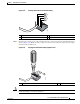
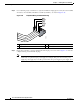
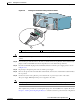
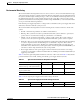
Figure 2-32 Inserting the Terminal Block Plug in the Block Header
Caution Secure the wires coming in from the terminal block plug so that they cannot be disturbed by casual
contact.
Step 10 Use a tie wrap to secure the wires to the rack, so that the wires are not pulled from the terminal block
plug by casual contact. Make sure the tie wrap allows for some slack in the ground wire.
Step 11 Insert the terminal block plug in the terminal block header on the DC power supply panel, as shown
in
Figure 2-32.
Step 12 Repeat Step 1 through Step 10 for the second DC power supply.
Step 13 Remove the tape from the circuit-breaker switch handle, and move the circuit-breaker switch handle to
the on
position.
Step 14 On the front of the router, place the power switch in the on position (O) to turn on the router.
The power supply LEDs light when power is supplied to the router.
Note After powering off the router, wait a minimum of 30 seconds before powering it on again.
This completes the procedure for connecting DC-input power. Your installation is complete. Proceed to
Chapter 3, “Starting and Configuring the Router,” to start the router and to perform a basic configuration.
1 Tie wrap 2 Terminal block plug
PWR
SLOT 2
B
A
170973
B
A
1
2