
Router Installation and Configuration Guide

2-32
Cisco 7201 Installation and Configuration Guide
OL-11364-04
Chapter 2 Installing the Cisco 7201 Router
Connecting Power
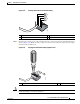
Step 8 Use a ratcheting torque screwdriver to torque the terminal block plug captive screw (above the installed
wire lead) to from 0.5 Nm (4.425 lbf in. to 0.6 Nm (5.310 lbf in.), as shown in
Figure 2-30.
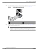
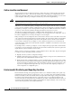
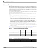
Figure 2-31 Completed Wiring of Terminal Block Plug
Step 9 Repeat Step 6 and Step 7 for the remaining three DC-input power source wires. Figure 2-31 shows the
completed wiring of a terminal block plug.
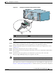
Note Each DC power supply accepts two power feeds, but works with only one. You may choose to
install only one power feed per power supply. For example, DC power feed A to the power
supply in power supply slot 1 and DC power feed B to the power supply in power supply slot 2.
1 Negative (–) 3 Negative (–)
2 Return (+) 4 Return (+)
170972
A
B
1
2
3
4