
Router Installation and Configuration Guide


2-25
Cisco 7201 Installation and Configuration Guide
OL-11364-04
Chapter 2 Installing the Cisco 7201 Router
Connecting Power
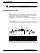
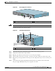
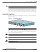
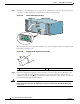
Figure 2-20 Power Supply Slot 1 and Slot 2
Warning
Never install an AC power module and a DC power module in the same chassis.
Statement 1050
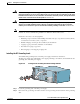
Connect an AC-input power supply as follows:
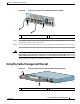
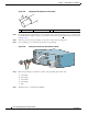
Figure 2-21 Connecting AC-Input Power
Step 1 At the front of the router, check that the power switch is in the standby (|) position.
Step 2 Swing the wire cable-retention clip to the left.
Step 3 Plug the power cable into the AC connector of one of the power supplies.
Step 4 Slide the cable-retention clip to the right, so that the power cable is held by the cable-retention clip.
Step 5 Plug the AC power supply cable into the AC power source. Repeat these steps for the second AC power
supply.
Step 6 On the front of the router, place the power switch in the on (O) position to turn on the router.
The power supply LEDs light when power is supplied to the router.
1 Power supply slot 1 2 Power supply slot 2
230086
PWR
SLOT 2
PWR
SLOT 1
PWR
SLOT 1 OK
T
H
I
S
U
N
I
T
M
A
Y
H
A
V
E
M
O
R
E
T
H
A
N
O
N
E
P
O
W
E
R
S
U
P
P
L
Y
C
O
N
N
E
C
T
IO
N
. A
L
L
C
O
N
N
E
C
T
IO
N
S
M
U
S
T
B
E
R
E
M
O
V
E
D
T
O
D
E
-
E
N
E
R
G
I
Z
E
T
H
E
U
N
IT
PWR
SLOT 2 OK
1
2
1 AC power receptacle 2 Adjustable AC power cable-retention clip
PWR
SLOT 2
158677
1
2