
Router Installation and Configuration Guide

2-13
Cisco 7201 Installation and Configuration Guide
OL-11364-04
Chapter 2 Installing the Cisco 7201 Router
Attaching a Chassis Ground Connection
Use the following procedure to attach the grounding lug to the chassis ground connector on your router
chassis:
Step 1 Use the wire stripper to strip one end of the 6-AWG wire approximately 0.75 inches (19.05 mm).
Step 2 Insert the 6-AWG wire into the wire receptacle on the grounding lug.
Step 3 Use the crimping tool to carefully crimp the wire receptacle around the wire; this step is required to
ensure a proper mechanical connection.
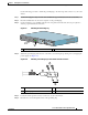
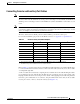
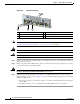
Figure 2-9 Attaching the Grounding Lug
Step 4 Attach the grounding lug with the wire on the left to avoid having the grounding wire overlapping the
power supply. See
Figure 2-9.
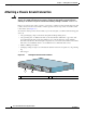
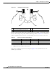
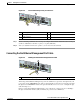
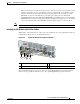
Figure 2-10 Attaching a Grounding Lug to the Chassis Ground Connector
Step 5 Locate the chassis ground connector on the rear of your router chassis.
Step 6 Insert the two screws through the holes in the grounding lug.
1 Grounding lug
230031
PWR
SLOT 2
PWR
SLOT 1
PWR
SLOT 1 OK
T
H
I
S
U
N
IT
M
A
Y
H
A
V
E
M
O
R
E
T
H
A
N
O
N
E
P
O
W
E
R
S
U
P
P
L
Y
C
O
N
N
E
C
T
I
O
N
. A
L
L
C
O
N
N
E
C
T
IO
N
S
M
U
S
T
B
E
R
E
M
O
V
E
D
T
O
D
E
-E
N
E
R
G
I
Z
E
T
H
E
U
N
IT
PWR
SLOT 2 OK
1
1 Chassis ground connector 3 Screws
2 Grounding lug 4 Wire
50536
1
2
3
4