
Router Installation and Configuration Guide

2-12
Cisco 7201 Installation and Configuration Guide
OL-11364-04
Chapter 2 Installing the Cisco 7201 Router
Attaching a Chassis Ground Connection
Attaching a Chassis Ground Connection
Warning
This equipment must be grounded. Never defeat the ground conductor or operate the equipment in the
absence of a suitably installed ground conductor. Contact the appropriate electrical inspection
authority or an electrician if you are uncertain that suitable grounding is available.
Statement 1024
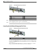
Before you connect power or turn on power to your router, you must provide an adequate chassis ground
(earth) connection for the router chassis. A chassis ground connector is provided on each Cisco 7201
router chassis. (See
Figure 2-8.)
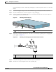
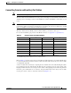
To ensure the chassis ground connection that you provide is adequate, you will need the following parts
and tools:
• One grounding lug—Ships on the chassis along with two M5 grounding screws
• One grounding wire—6-AWG, 0.162-inch (4.115-mm) diameter multistrand, copper wire, with
approximately 0.108-inch (2.743-mm) insulation, for a total wire diameter of approximately
0.27
inches (6.858 mm). The wire length is dependent on your router location and site environment.
This wire is not available from Cisco; it is available from a commercial cable vendor.
• Number 2 Phillips screwdriver
• Crimping tool large enough to accommodate the diameter of the wire receptacle on your grounding
lug
• Wire stripper
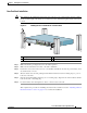
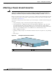
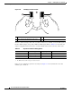
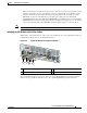
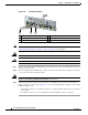
Figure 2-8 Locating the Chassis Ground Connector
1 Fan vents 2 Chassis ground connector
170934
PWR
SLOT 2
PWR
SLOT 1
PWR
SLOT 1 OK
T
H
IS
U
N
IT
M
A
Y
H
A
V
E
M
O
R
E
T
H
A
N
O
N
E
P
O
W
E
R
S
U
P
P
L
Y
C
O
N
N
E
C
T
IO
N
.
A
L
L
C
O
N
N
E
C
T
IO
N
S
M
U
S
T
B
E
R
E
M
O
V
E
D
T
O
D
E
-
E
N
E
R
G
IZ
E
T
H
E
U
N
IT
PWR
SLOT 2 OK
2
1