
Router Installation and Configuration Guide

2-7
Cisco 7201 Installation and Configuration Guide
OL-11364-04
Chapter 2 Installing the Cisco 7201 Router
Installing the Router
Attaching the Chassis Rack-Mount and Cable-Management Brackets
This section explains how to install the rack-mount and cable-management brackets at the front and the
rear of a Cisco 7201 router. Before installing the chassis in the rack, you must install a rack-mount
bracket on each side of the front or rear of the chassis.
The parts and tools required for installing the rack-mount brackets and cable-management bracket are
listed in the
“Tools and Parts Required” section on page 2-3.
Installing Rack-Mount Brackets on the Front of the Chassis
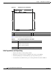
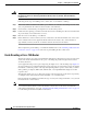
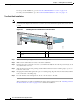
Figure 2-3 Attaching the Rack-Mount Brackets to the Front of the Chassis
Figure 2-3 shows the brackets being attached for a front rack-mount.
To install the rack-mount and cable-management brackets on a Cisco 7201 router for a front rack-mount
configuration, complete the following steps:
Step 1 Locate the threaded holes in the front sides of the chassis.
Step 2 Align the rack-mount bracket to the rack-mount bracket holes on the side of the router.
Step 3 Remove any existing cover screws from the front sides of the chassis that align with the rack-mount
bracket holes and then realign the bracket. (You should have to remove one cover screw from each side
of the chassis.)
Step 4 Insert and tighten two 6-32 x 0.25-in. screws in the two holes nearest the front of the chassis.
Step 5 Insert and tighten the longer M3 x 8-mm screw in the hole nearest the rear of the chassis. (This screw
replaces the cover screw that you removed in Step 3.)
Step 6 Repeat Step 1 through Step 5 on the other side of the router.
This completes the steps for attaching the rack-mount brackets to the Cisco 7201 router.
1 Rack-mount bracket 3 Two M3 x 8-mm screws
2 Four 6-32 x 0.25-in. screws
281124
E
N
A
B
L
E
D
R
X
C
E
L
LS
R
X
C
A
R
R
IE
R
R
X
A
LA
R
M
A
T
M
G
E
0/0
G
E 0/1
G
E 0/2
G
E
0/3
AU
X
CO
NSO
LE
M
N
G
M
N
T U
S
E O
N
LY
F
E
L
INK
0
FE 0/0
RJ45
SF
P
S
FP
S
FP
S
FP
LIN
K/A
C
TV
ALAR
M
PW
R O
K
STATUS
CF
AC
T
V
C
O
M
PA
CT FLASH
LINK
/A
C
TV
R
X
T
X
LINK
/A
CT
V
L
INK
/ACT
V
R
X
TX
EN
RJ45
EN
PA
SLO
T 1
2 31
Cisco 7201