
Router Installation and Configuration Guide

1-9
Cisco 7201 Installation and Configuration Guide
OL-11364-04
Chapter 1 Overview
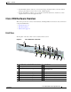
Cisco 7201 Hardware Overview
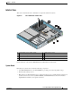
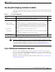
Interior View
This section describes the Cisco 7201 interior components and their locations.
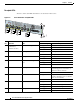
Figure 1-6 Cisco 7201 Router—Interior View
On the underside of the board is NVRAM (U77) and flash memory (U67, U70).
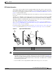
System Board
Internally, the system board contains the following components:
• One DDR-SDRAM memory module (DIMM) for providing code, data, and packet storage
• The Freescale 7448 processor
• Marvel Discovery III—Hardware logic to interconnect the processor, double data rate synchronous
dynamic random-access memory (DDR-SDRAM), dual PCI /PCI-X buses, three direct-interface
Gigabit Ethernet interfaces, and a generic device bus
1 Temperature sensor (outlet—U20) 5 Flash memory (U13)
2 Freescale 7448 processor 6 Temperature sensor (inlet—U12)
3 Boot ROM (U24) 7 DIMM (U16)
4 Flash memory (U19)
170955
E
N
A
B
L
E
D
RX CELLS
RX CARRIER
RX ALARM
ATM
A
L
A
R
M
R
J
4
5
E
N
L
IN
K
T
X
R
X
G
B
IC
G
IG
A
B
IT
E
T
H
E
R
N
E
T
0
/2
R
J
4
5
E
N
L
IN
K
T
X
R
X
G
B
IC
G
IG
A
B
IT
E
T
H
E
R
N
E
T
0
/
0
R
J4
5
E
N
L
IN
K
T
X
R
X
G
B
IC
G
IG
A
B
IT
E
T
H
E
R
N
E
T
0
/1
CISC
O 7301
S
LO
T
1
C
O
N
S
O
L
E
A
U
X
C
O
M
P
A
C
T
F
L
A
S
H
S
T
A
T
U
S
1
0
0
-2
40
V
, 2
A
, 5
0
/60
H
z
24
V
=
9
A
, 4
8
- 6
0
V
=
5
A
BA
E
N
A
B
L
ED
RX
CELLS
RX CA
RRIER
RX ALA
RM
ATM
GE 0/0
G
E 0/1
G
E 0/2
GE 0/3
A
UX
CO
NS
OLE
MNG
M
NT
U
SE O
NLY
FE
LIN
K
0
FE 0/0
RJ
45
SFP
SFP
SFP
SFP
LINK/A
CTV
ALAR
M
PW
R O
K
STATU
S
CF
AC
TV
C
O
M
P
A
C
T
F
L
A
S
H
LIN
K/A
CTV
R
X
TX
LIN
K/ACTV
LINK/ACTV
R
X
TX
EN
RJ45
E
N
PA
SLO
T 1
2
1
3
4
5
6
7
Cisco
7201