
Router Installation and Configuration Guide

1-4
Cisco 7201 Installation and Configuration Guide
OL-11364-04
Chapter 1 Overview
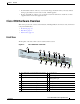
Cisco 7201 Hardware Overview
Faceplate LEDs
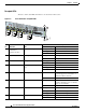
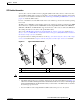
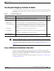
The Cisco 7201 router LEDs and behaviors are described in this section.
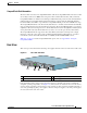
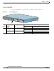
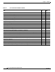
Figure 1-2 Cisco 7201 Router—Faceplate LEDs
No. LED Label LED
In the Power Up State
Color—Activity Behavior Description
1 LINK/ACTV
(Link/Active)
(0/0, 0/1, 0/2, 0/3)
SFP and RJ-45 ports Solid green Link with no activity
Flashing green Link with activity
Off No link
2 EN (Enable) (0/0, 0/1) RJ-45 ports only Solid green RJ-45 port is selected.
Off SFP port is selected.
3 USB USB port Flashing green Activity
Off No activity
4 FE 0/0 Fast Ethernet Management
port
Solid green Link with no activity
Flashing green Link with activity
Off No link
5 ALARM Alarm port Solid red On if Cisco IOS has crashed, and a
reset has happened, and remains on
until Cisco IOS is reloaded.
Off Off, the system is normal.
6 PWR OK Power Solid green The power-on is successful and the
system is attempting to boot software,
or has booted software.
Off Off, the router is in standby mode.
7 STATUS System status Solid green Cisco IOS has successfully booted.
Blinking amber ROMmon is loading.
Blinking green Cisco IOS is loading.
8 CF ACTV CompactFlash Disk Flashing green Activity
Off No activity
GE 0/0
GE 0/1
GE 0/2
GE 0/3
AUX
CONSOLE
MNGMNT USE ONLY
FE
LINK
0
FE 0/0
RJ45
SFP
SFP
SFP
SFP
LINK/ACTV
ALARM
PWR OK
STATUS
CF
ACTV
COMPACT FLASH
LINK/ACTV
RX
TX
LINK/ACTV
LINK/ACTV
RX
TX
EN
RJ45
EN
170859
5
6
7
8
1
2
1
2
1
1
3
4
Cisco
7201