
Router Installation and Configuration Guide

1-3
Cisco 7201 Installation and Configuration Guide
OL-11364-04
Chapter 1 Overview
Cisco 7201 Hardware Overview
• Downloadable software—Allows you to load new images into flash memory remotely, without
having to physically access the router, for fast, reliable upgrades
• Front-to-back airflow—Allows you to mount the router from either front or back into 19-inch
equipment racks and 23-inch equipment racks
Cisco 7201 Hardware Overview
This section provides an overview of the hardware, including LEDs, front and rear views, and interior
component identification.
• Front View, page 1-3
• Rear View, page 1-7
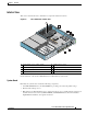
• Interior View, page 1-9
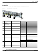
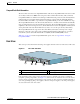
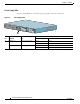
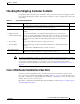
Front View
The faceplate of the Cisco 7201 router is described in this section.
Figure 1-1 Cisco 7201 Router—Front View
1 Port adapter slot (with installed port adapter) 9 Console port
2 Port adapter lever 10 Auxiliary port
3 Gigabit Ethernet 0/0—RJ-45 port 11 Fast Ethernet 0/0—Fast Ethernet
Management port
4 Gigabit Ethernet 0/0—SFP port 12 USB port
5 Gigabit Ethernet 0/1—RJ-45 port 13 Power switch
6 Gigabit Ethernet 0/1—SFP port 14 CompactFlash Disk slot
7 Gigabit Ethernet 0/2—SFP port 15 CompactFlash Disk ejector button
8 Gigabit Ethernet 0/3—SFP port
170858
ENABLED
RX CELLS
RX CARRIER
RX ALARM
AT M
GE 0/0
GE 0/1
GE 0/2
GE 0/3
AUX
CONSOLE
MNGMNT USE ONLY
FE
LINK
0
FE 0/0
RJ45
SFP
SFP
SFP
SFP
LINK/ACTV
ALARM
PWR OK
STATUS
CF
ACTV
COMPACT FLASH
LINK/ACTV
RX
TX
LINK/ACTV
LINK/ACTV
RX
TX
EN
RJ45
EN
PA
SLOT 1
Cisco
7201
1
2
4
6
8
9
11
13
3
5
7
10
12
14
15