
Router Installation and Configuration Guide

A-10
Cisco 7201 Installation and Configuration Guide
OL-11364-04
Appendix A Specifications
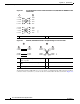
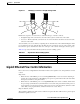
Console Port and Auxiliary Port Signals and Pinouts
Console Port and Auxiliary Port Signals and Pinouts
Note The console cable kit product number is ACS-2500ASYN.
The Cisco 7201 router does not support Data Carrier Detect (DCD).
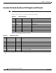
Table A-14 lists the RJ-45 auxiliary port signals.
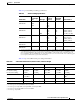
Ta ble A-13 Console Port Signals
Pin Signal Direction Description
1
CTS Out Clear to Send (tied to pin 8)
2
DSR Out Data Set Ready
3
RXD Out Receive Data
4
GND — Signal Ground
5
GND — Signal Ground
6
TXD In Transmit Data
7
DTR In Data Terminal Ready
8
RTS In Ready to Send (tied to pin 1)
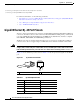
Ta ble A-14 Auxiliary Port Signals
Pin Signal Direction Description
1
RTS Out Ready to Send
2
DTR Out Data Terminal Ready
3
TXD Out Transmit Data
4
RING
1
1. RING is not supported on Cisco-supplied adapters. To use this pin, you must create a customized cable.
In Ring Indication
5
GND — Signal Ground
6
RXD In Receive Data
7
2
2. Pin 7 can be used as a DCD input for connection to a modem. The RJ-45-to-DB-25F adapter maps DCD to this pin when used with a straight-through
cable.
DSR/DCD (RLSD) In Data Set Ready/Data Carrier Detect (Receive Line Signal Detect)
8
CTS In Clear to Send (tracks RTS)