
Router Installation and Configuration Guide

A-7
Cisco 7201 Installation and Configuration Guide
OL-11364-04
Appendix A Specifications
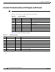
Gigabit Ethernet RJ-45 Port Pinouts
Note With reference to the RJ-45 pinouts in Table A-11, proper common-mode line terminations should be
used for the unused Category 5 UTP cable pairs 4/5 and 7/8. Common-mode line termination reduces
electromagnetic interference (EMI).
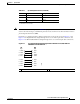
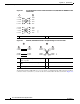
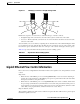
Depending on your RJ-45 interface cabling requirements, use the pinouts shown in Figure A-2 and
Figure A-3 for Gigabit Ethernet straight-through and crossover twisted-pair cable connections. Use
Figure A-4 for Ethernet/Fast Ethernet straight-through and crossover twisted-pair cable connections.
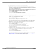
Figure A-2 Four Twisted-Pair Straight-Through Cable Schematics for 10/100/1000 and
1000BASE-T SFP Module Ports
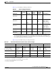
6 RX DATA– Rx B–
7 N/C Rx D+
8 N/C Rx D–
1. TX DATA = Transmit Data
2. RX DATA = Receive Data
Table A-11 RJ-45 Receptacle Pinouts (continued)
Pin FE Signal GE Signal
1 Router 2 Hub
1 2
1 TPO+
2 TPO-
3 TP1+
6 TP1-
1 TP1+
2 TP1-
3 TPO+
6 TPO-
4 TP2+
5 TP2-
7 TP3+
8 TP3-
4 TP3+
5 TP3-
7 TP2+
8 TP2-
129086