
Router Installation and Configuration Guide

A-5
Cisco 7201 Installation and Configuration Guide
OL-11364-04
Appendix A Specifications
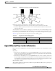
SFP Module Specifications and Configurations
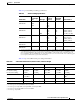
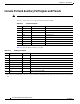
Table A-9 provides SFP port cabling specifications.
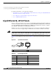
Table A-10 provides SFP module power budget information.
Ta ble A-9 SFP Port Cabling Specifications
SFP Module
Wavelength
(nm) Fiber Type
Core Size
(microns)
Modal
Bandwidth
(MHz/km) Cable Distance
100BASE-FX
SFP-GE-F=
1270
1300
1380
MMF 62.5
2.5
50.0
50.0
500 6562 ft. (2 km)
1000BASE-LX/LH
SFP-GE-L=
1300 MMF
1
SMF
1. A mode-conditioning patch cord is required. Using an ordinary patch cord with MMF, 1000BASE-LX/LH SFP modules, and
a short link distance (tens of meters) can cause transceiver saturation resulting in an elevated bit error rate (BER). In addition,
when using the LX/LH SFP module with 62.5-micron diameter MMF, you must install a mode-conditioning patch cord
between the SFP module and the MMF cable on both the transmit and receive ends of the link. The mode-conditioning patch
cord is required for link distances greater than 984 ft (300 m).
62.5
50.0
50.0
9/10
500
400
500
—
1804 ft (550 m)
1804 ft (550 m)
1804 ft (550 m)
6.2 miles (10 km)
1000BASE-SX
SFP-GE-S=
850 MMF 62.5
62.5
50.0
50.0
160
200
400
500
722 ft (220 m)
902 ft (275 m)
1640 ft (500 m)
1804 ft (550 m)
1000BASE-ZX
SFP-GE-Z=
1550 SMF 9/10 — 229670 ft (70 km)
1000BASET
SFP-GE-T=
N/A Copper N/A N/A 328 ft. (100 m)
Ta ble A-10 SFP Module Transmit Power, Receive Power, and Power Budget
SFP Module Transmit Power Receive Power Power Budget
Minimum Maximum Minimum Maximum
SFP-GE-F=
For 50/125 cabling
For 62.5/125 cabling
-23.5 dBm
-20 dBm
-14 dBm
-14 dBm
-33.5 dBm
-33.5 dBm
-11.8 dBm
-11.8 dBm
10 dBm
13.5 dBm
SFP-GE-L= –9.5 dBm
1
–11.5 dBm
2
1. For fiber types 9/125 µm SMF.
2. For fiber types 62.5/125 µm MMF and 50/125 µm MMF.
–3 dBm
3
3. For fiber types 9/125 µm SMF, 62.5/125 µm MMF, and 50/125 µm MMF.
–20 dBm –3 dBm 7.5 dBm
4
and 8.0
dBm
5
4. For fiber types 50/125 µm MMF and 62.5/125 µm MMF.
5. For fiber type 10 µm SMF.
SFP-GE-S= –9.5 dBm
6
–4 dBm
6
–17 dBm 0 dBm 7.5 dBm
7
SFP-GE-Z= 0 dBm 5 dBm –23 dBm 0 dBm –24 dBm