
Router Installation and Configuration Guide


4-18
Cisco 7201 Installation and Configuration Guide
OL-11364-04
Chapter 4 Replacing Cisco 7201 Field-Replaceable Units
Removing and Installing a DIMM
Replacing the Cover and Powering On the Router
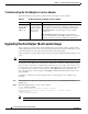
The Cisco 7201 router cover fits tightly on the chassis. Follow these instructions to replace the cover and
power on the router:
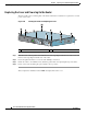
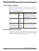
Figure 4-15 Inserting the Screws and Replacing the Cover
Step 1 Place the cover on the top of the router with the four-screw edge aligned with the front of the router, and
the five-screw edge aligned with the rear of the router.
Step 2 Insert and tighten the fifteen cover screws with a Phillips screwdriver.
Step 3 Return the router to its installation site, attach the ground cable, and input/output and power cables.
Step 4 Power on the router by turning the power switch to the on position.
This completes the installation of the DIMM and replacement of the cover.
1 Cover screws
170954
PWR
SLOT 2
PWR
SLOT 1
PWR
SLOT 1 OK
T
H
IS
U
N
IT
M
A
Y
H
A
V
E
M
O
R
E
T
H
A
N
O
N
E
P
O
W
E
R
S
U
P
P
L
Y
C
O
N
N
E
C
T
IO
N
.
A
L
L
C
O
N
N
E
C
T
IO
N
S
M
U
S
T
B
E
R
E
M
O
V
E
D
T
O
D
E
-
E
N
E
R
G
IZ
E
T
H
E
U
N
IT
PWR
SLOT 2 OK
1