
Router Installation and Configuration Guide

4-8
Cisco 7201 Installation and Configuration Guide
OL-11364-04
Chapter 4 Replacing Cisco 7201 Field-Replaceable Units
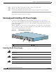
Removing and Installing an AC Power Supply
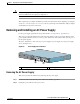
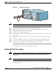
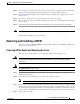
Figure 4-6 Removing the AC Power Cable
Step 3 Swing the cable-retention clip to the left.
Step 4 Unplug the AC power cable from the power supply.
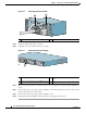
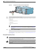
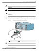
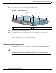
Figure 4-7 Removing the AC Power Supply
Step 5 Move the power up restrictor to the left to gain access to the upper power supply captive installation
screw.
Step 6 Unscrew the upper power supply captive installation screw while holding the power up restrictor to the
left, then release the power up restrictor.
Step 7 Unscrew the lower power supply captive installation screw.
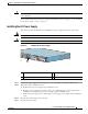
Step 8 Grasping the captive installation screws, pull the power supply from the chassis.
1 AC power receptacle 2 AC power cable-retention clip
PWR
SLOT 2
158677
1
2
1 Power up restrictor 3 Lower power supply captive installation
screw
2 Upper power supply captive installation screw
170934
PWR
SLOT 2
PWR
SLOT 1
PWR
SLOT 1 OK
.
A
L
L
C
O
N
N
E
C
T
IO
N
S
M
U
S
T
B
E
R
E
M
O
V
E
D
T
O
D
E
-
E
N
E
R
G
IZ
E
T
H
E
U
N
IT
PWR
SLOT 2 OK
2