
Router Installation and Configuration Guide

4-6
Cisco 7201 Installation and Configuration Guide
OL-11364-04
Chapter 4 Replacing Cisco 7201 Field-Replaceable Units
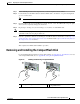
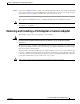
Removing and Installing a Port Adapter or Service Adapter
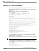
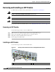
Figure 4-4 Installing a Port Adapter or Service Adapter
Follow these steps for inserting and securing a port adapter:
Step 1 Attach an ESD-preventative wrist strap between you and an unpainted chassis surface.
Step 2 Disconnect all cables from the port adapter.
Step 3 Remove the port adapter from the chassis slot by sliding the port adapter lever to the right, in the
unlocked position.
Step 4 Grasp the handle and pull the port adapter or port adapter blank panel from the router.
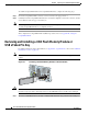
Step 5 Locate the port adapter slot guides inside the Cisco 7201 router. They are near the top, and are recessed
about one-half inch.
Caution The port adapter must slide into the slot guides under the chassis lid. Do not allow the port adapter
components to come in contact with the system board or the port adapter could be damaged.
Step 6 Carefully slide the port adapter into the port adapter slot and seat it. When installed, the port adapter
input/output panel should be flush with the face of the router.
Step 7 Slide the port adapter lever left to the locked position.
Step 8 Reconnect any cables, including the port adapter and power cables, and place the cables through any
cable-management bracket or power cable-retention clip.
Step 9 Power on the router by turning the power switch to the on (O) position.
Note If the port adapter fails to come up, reseat or reinsert the port adapter: do not use excessive force.
1 Port adapter lever 3 Port adapter slot guide
2 Port adapter
170872
A
L
A
R
M
R
J4
5
E
N
L
IN
K
T
X
R
X
G
B
IC
G
IG
AB
IT
E
T
HE
R
N
E
T
0
/
2
R
J4
5
E
N
L
IN
K
TX
R
X
G
BI
C
G
IG
A
B
IT
E
T
H
E
R
N
E
T
0
/0
R
J
4
5
E
N
L
I
N
K
T
X
R
X
G
B
IC
G
IG
A
B
I
T
E
T
H
E
R
N
E
T
0/1
C
ISC
O
730
1
S
L
O
T
1
C
O
N
S
O
L
E
A
U
X
C
O
M
P
A
C
T
FL
A
S
H
S
T
A
T
U
S
1
0
0
-
24
0
V
,
2
A
,
5
0/
6
0
H
z
2
4V
=
9
A
, 4
8
- 6
0
V
=
5
A
G
E
0
/
0
G
E
0
/1
G
E
0
/
2
G
E
0
/
3
A
U
X
C
O
N
S
O
L
E
M
N
G
M
N
T
U
S
E
O
N
L
Y
F
E
L
IN
K
0
F
E
0
/
0
R
J
4
5
S
F
P
S
F
P
S
F
P
S
F
P
L
IN
K
/
A
C
T
V
A
L
A
R
M
P
W
R
O
K
S
T
A
T
U
S
C
F
A
C
T
V
CO
MPACT FLASH
L
IN
K
/
A
C
T
V
R
X
T
X
L
IN
K
/
A
C
T
V
L
I
N
K
/A
C
T
V
R
X
T
X
E
N
R
J
4
5
E
N
ENABLED
R
X
C
E
L
L
S
R
X
C
A
R
R
IE
R
R
X
A
L
A
R
M
ATM
2
3
1
Cisco 7201